
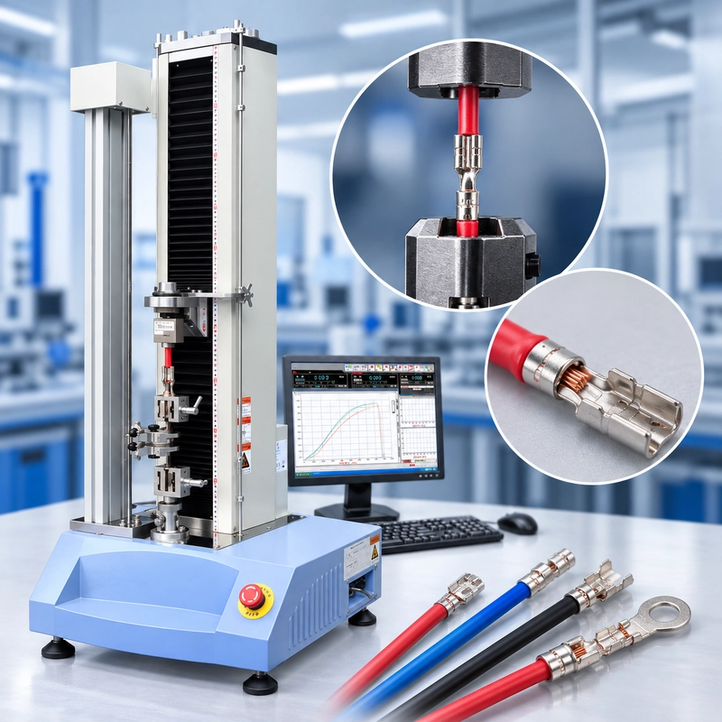
A typical RFQ for a wire-terminal pull tester might read:
18 AWG wire.
Crimp terminal pull test.
Minimum requirement: 100 N.
Need a pull-test machine.
It sounds specific, but there is not enough information yet to select the test system.
The 100 N figure may be the minimum force the finished crimp is required to withstand. It does not tell us how much force a good connection will actually generate before failure. Nor does it tell us how the terminal should be held, how much free wire is available for gripping, or which specification defines the test conditions.
Before selecting a load cell, we would normally ask for the terminal drawing or sample, wire construction, applicable test requirement, expected break-force range and daily sample volume.
That is the practical starting point for a crimp pull test: define the connection and test conditions before choosing the machine.
What Does a Crimp Pull Test Measure?
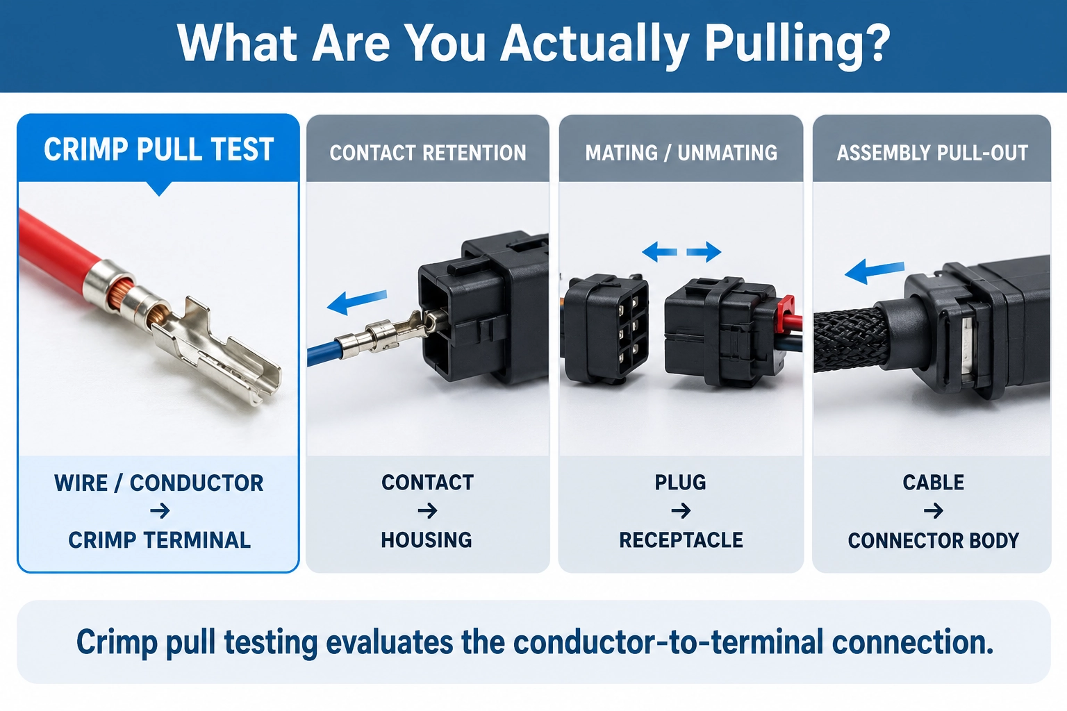
In this guide, crimp pull testing means applying tensile load to the connection between a wire conductor and its crimped terminal or contact.
That boundary is important because several connector tests can look similar once the specimen is mounted in a force tester.
Pulling the conductor from the crimp barrel is a crimp tensile test. Pulling a contact from its connector housing is a contact-retention test. Pulling two connector halves apart is a mating or unmating-force test.
They may all produce results in newtons, but they evaluate different interfaces.
For a crimp pull test, the connection of interest is:
Conductor → Crimp Barrel → Terminal
The test evaluates the mechanical integrity of that connection under the conditions defined by the applicable test method and product requirement.
If your application involves pulling the terminal from the housing rather than the conductor from the crimp, see our Connector Pull-Out Force Test
IEC 60352-2, EIA-364-08C and Product Requirements
Two references frequently appear in wire-terminal crimp testing.
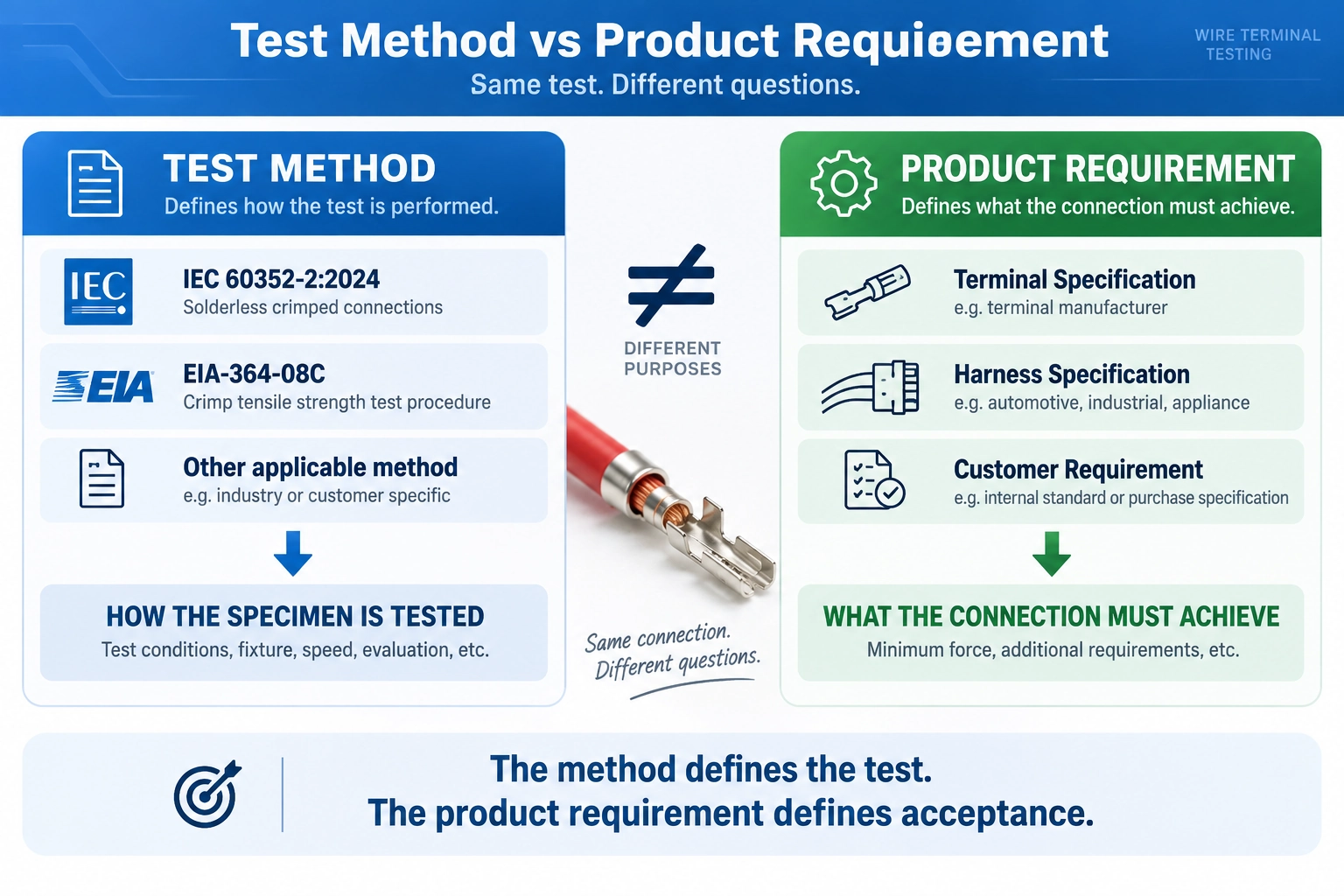
IEC 60352-2:2024 covers solderless crimped connections within its defined scope and provides requirements, test methods and practical guidance for crimped connections.
EIA-364-08C addresses crimp tensile strength testing for electrical connector contacts and conductors.
For equipment selection, however, knowing the standard number is only part of the job.
The test method establishes how the connection is tested. The applicable terminal, harness, product or customer specification establishes what the finished connection is expected to achieve.
This distinction matters when someone finds a pull-force table online and assumes that the value shown for a particular wire size automatically becomes the acceptance criterion for every terminal using that conductor.
It does not.
If an RFQ simply says “IEC crimp pull test,” we would still ask for the exact applicable method and the cable, harness, terminal or customer specification being used.
Why Two Good-Looking Crimps Can Produce Different Pull Forces
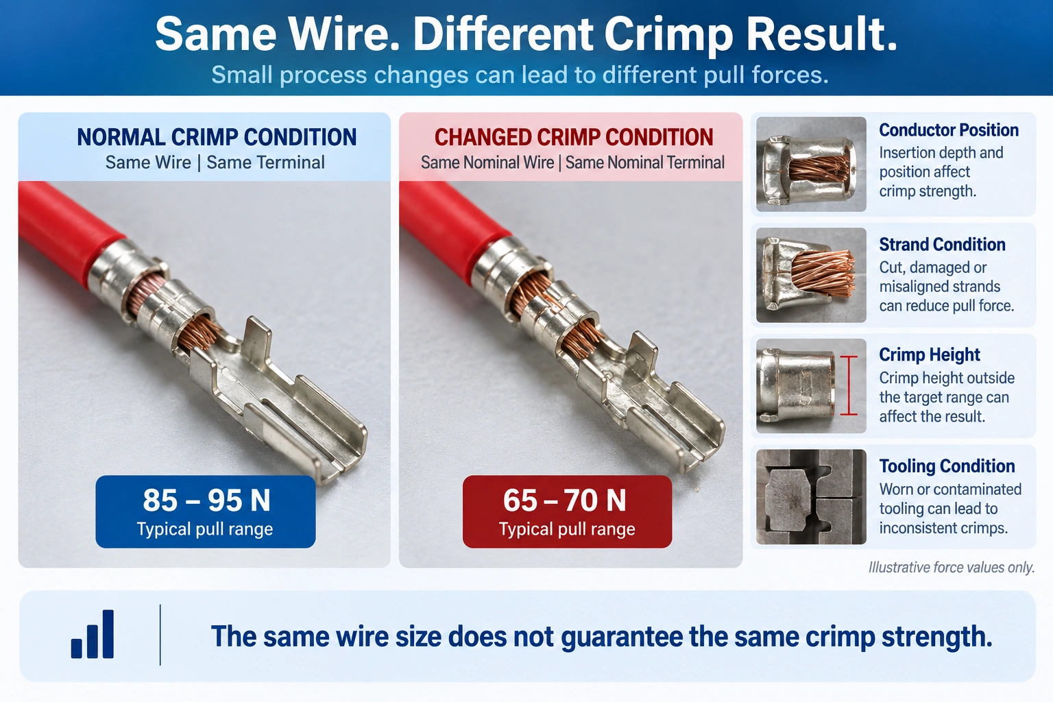
A crimp pull test is often treated as a final inspection of a finished terminal. On a production line, it is more useful to think of the result as one output of the entire crimping process.
Suppose a line normally produces pull results around 85–95 N. During one shift, several samples begin failing in the high-60 N range.
The wire size has not changed. Neither has the terminal part number or the pull-test machine.
The tester would not be the first thing worth blaming.
The investigation should move upstream. Has the conductor insertion changed? Were strands cut during stripping? Is the crimp height still within the process target? Is the terminal sitting correctly in the applicator? Is the tooling worn or contaminated?
A finished crimp can look acceptable from the outside while its mechanical behavior has already changed.
This is one reason pull testing is useful for crimp quality control. A shift in the test results can help expose a process change before that change becomes obvious from visual inspection alone.
Why the Fixture Matters in a Wire Terminal Pull Test
In many crimp applications, fixture design matters more than buying a larger tensile frame.
The two ends of the specimen present completely different gripping problems. One is flexible wire; the other may be a ring terminal, blade terminal, open-barrel terminal or small connector contact.
They should not simply be treated as two conventional tensile specimens.
Holding the terminal
The terminal has to remain restrained during the pull without the fixture artificially supporting the connection being evaluated.
The solution depends heavily on geometry.
A ring terminal can often be located around a suitable pin. A small contact may need a slotted plate or geometry-specific holder. Other terminal shapes require their own restraint arrangement.
The objective is not maximum clamping pressure. It is repeatable restraint with a controlled load path.
Holding the wire
The opposite end creates a different problem.
A wire grip that works well on a relatively thick PVC-insulated lead may not work equally well with a smaller or softer wire.
Too little grip can allow slip. Too much localized pressure can damage the insulation or conductor and create a new failure point at the jaw edge.
Available free wire length also matters. A perfectly valid production assembly may leave very little straight wire between the terminal and another component, making specimen loading more difficult than the force range itself suggests.
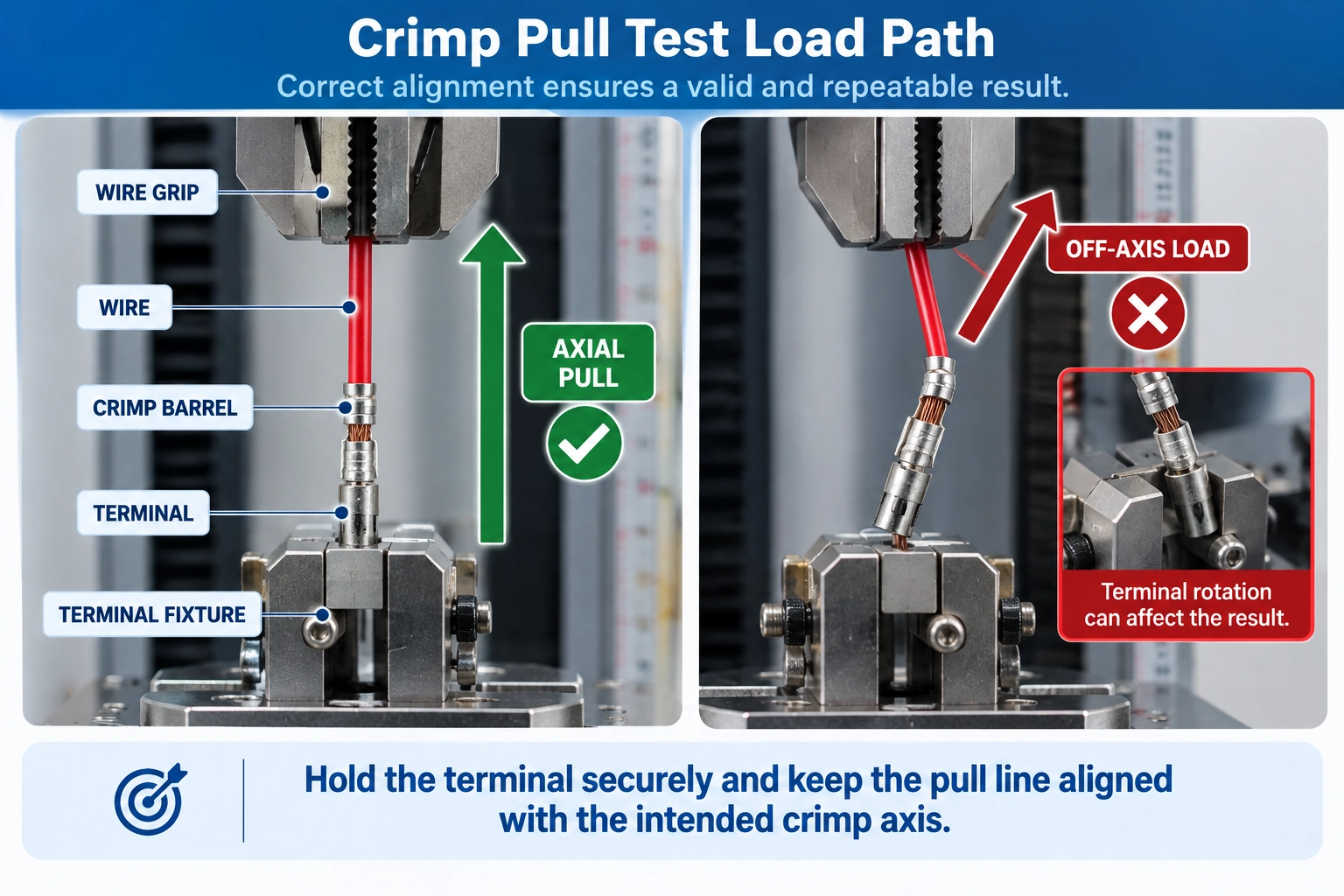
Keeping the pull aligned
Alignment is the third part of the fixture problem.
If the pull line does not pass through the intended crimp axis, some of the applied machine force can be used to bend or rotate the terminal instead of loading the crimped connection primarily in tension.
The force reading may still look perfectly normal on the screen.
The load path may not be.
Was the Crimp Weak—or Did the Test Setup Fail?
When a result looks wrong, inspect the specimen before changing the production process.
A low peak force can come from the crimp itself. It can also come from the way the specimen was mounted.
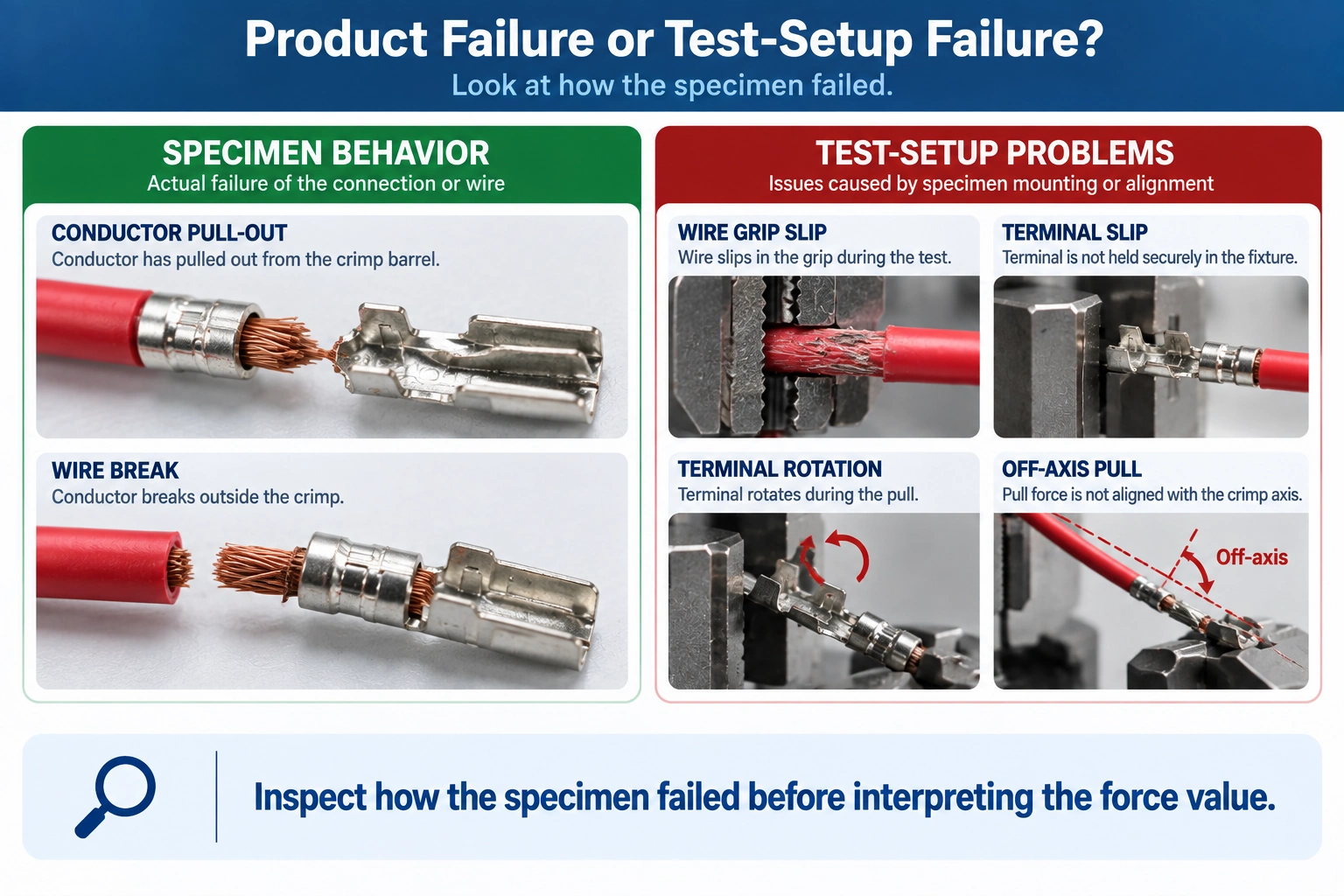
The distinction becomes easier if the observations are separated into two groups.
Specimen behavior
Conductor pull-out means the conductor has separated from the crimped connection. The resulting force can then be evaluated according to the applicable requirement.
Wire breakage is a different event. The conductor failed rather than simply pulling free from the barrel, so the result should be interpreted according to the applicable method rather than automatically classified as equivalent to pull-out.
Test-setup problems
Wire grip slip means movement occurred between the specimen and grip.
Terminal slip means the restraint did not hold the terminal consistently.
Terminal rotation or bending may indicate that the fixture geometry does not suit the specimen.
Off-axis pulling introduces a load component that was not intended in a straightforward axial tensile test.
A low result caused by wire slipping in the grip should not automatically be treated as evidence of a weak crimp.
Likewise, if several specimens consistently bend in the same direction before failure, the fixture deserves inspection before the crimping machine is adjusted.
When the Force-Displacement Curve Is Useful
For routine production checks, peak force may be all the specification requires.
The curve becomes more useful when results begin behaving differently or when a new test setup is being developed.
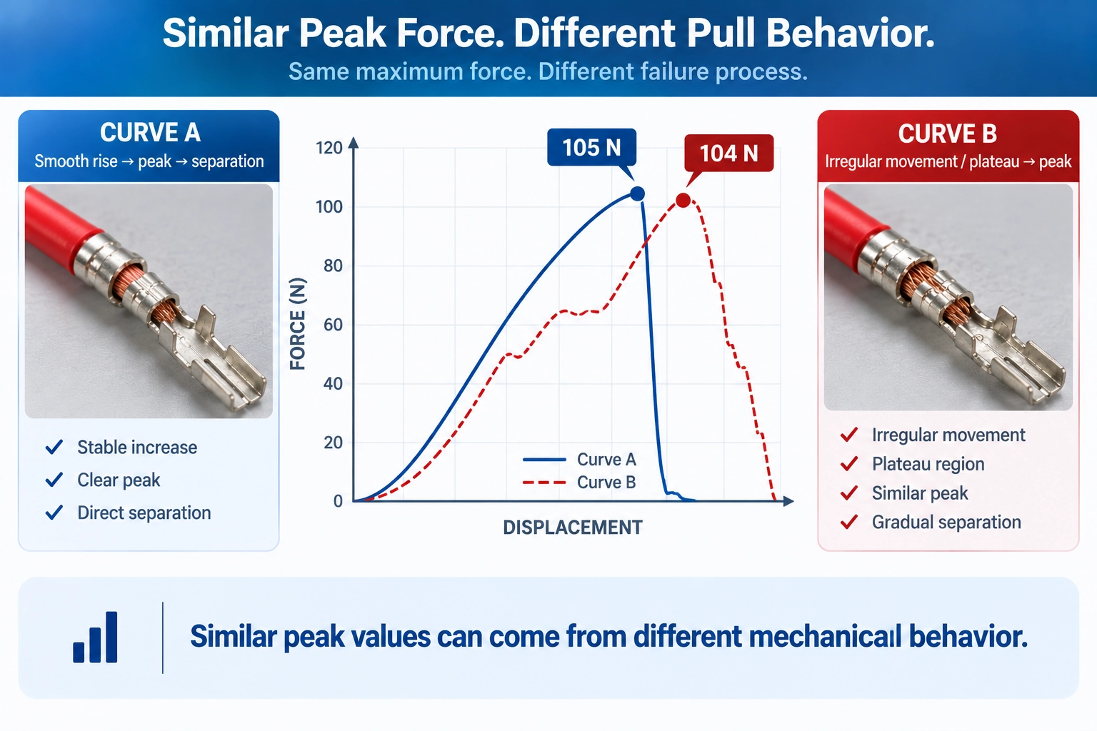
Consider two specimens:
Sample A: 105 N peak
Sample B: 104 N peak
On a pass/fail report, they look almost identical.
The curves may tell a different story.
Sample A might rise smoothly to a distinct maximum before separation. Sample B might show an irregular plateau and substantially more movement before reaching a similar peak.
That pattern does not, by itself, diagnose a particular crimp defect. The extra movement could come from the specimen, terminal movement, wire slip or another part of the setup.
What the curve does show is that the two tests did not behave in the same way.
For development, troubleshooting or process comparison, that information can be valuable. For repetitive production QC, peak force plus a clear observation of the failure mode may be sufficient.
Why an 80 N Requirement Does Not Mean You Need an 80 N Tester
This is one of the easiest mistakes to make when specifying a crimp pull test machine.
Suppose the product requirement says:
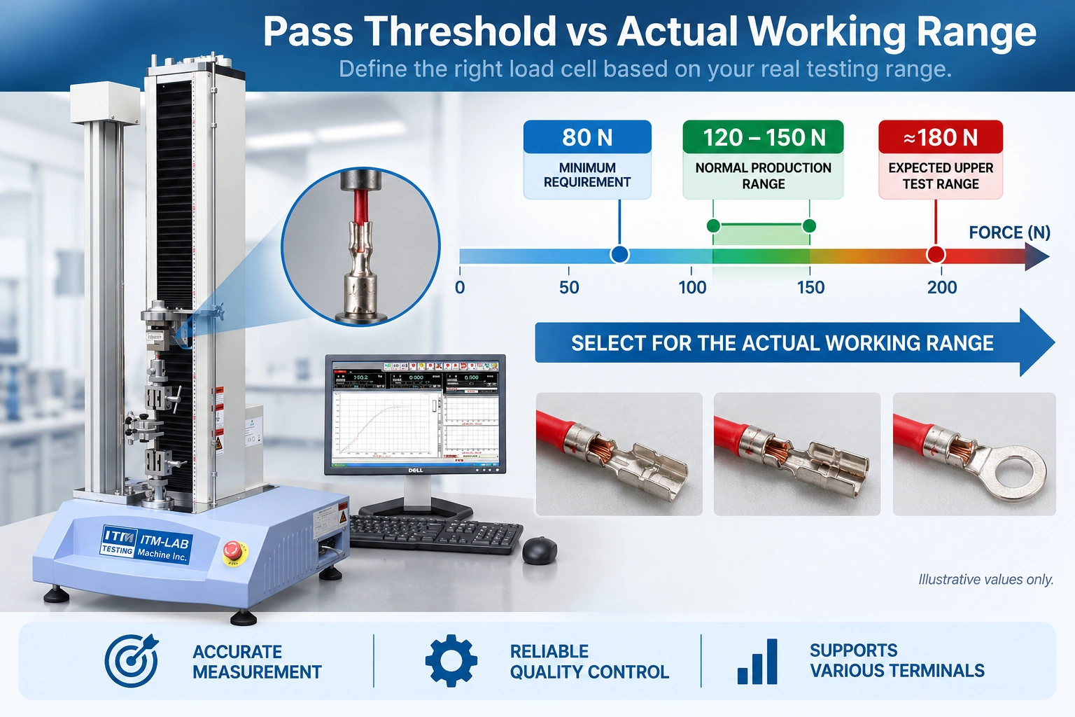
Minimum pull force: 80 N
That is an acceptance threshold. It does not mean a good connection will fail at 80 N.
Imagine that historical production data show normal results around 120–150 N, while particularly strong specimens can approach 180 N before failure.
The test system still has to measure those specimens.
| Test Information | Example Value |
|---|---|
| Minimum acceptance requirement | 80 N |
| Normal production range | 120–150 N |
| Expected upper test force | ≈180 N |
These values are illustrative, not universal crimp requirements.
The equipment lesson is what matters:
the load cell needs to cover the actual working-force range, not merely the pass threshold.
Going to the opposite extreme is not necessarily better. Installing a much larger load cell simply because it offers more capacity can be unnecessary when the entire application is low force.
For a machine supplier, two force values are therefore more useful than one:
What is the minimum acceptance requirement?
and
What is the highest force you reasonably expect a specimen to generate before failure?
How to Select a Crimp Pull Test Machine
Once the specimen and working-force range are understood, equipment selection becomes much more straightforward.
A practical sequence is:
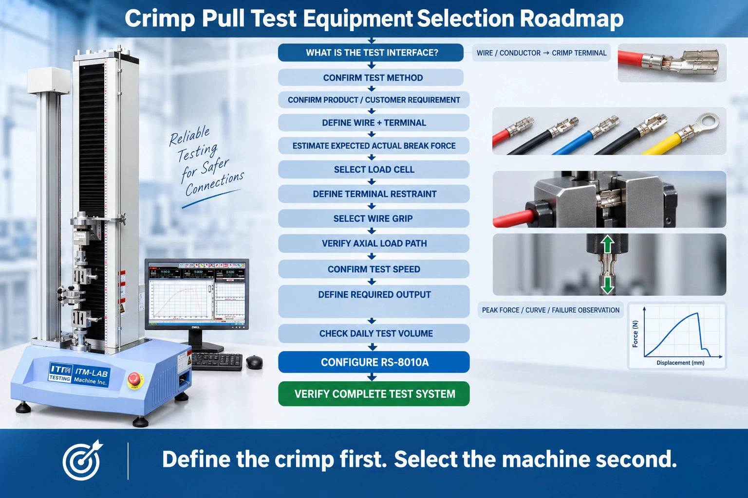
Wire and terminal → expected break force → load cell → terminal fixture → wire grip → alignment → test speed → required result → daily volume → machine configuration
That order is intentional.
Low-force terminal testing is often limited by measurement range and specimen handling rather than by the maximum capacity of the tensile frame.
A machine can have far more than enough force capacity and still be inconvenient for the job if the terminal cannot be located consistently or the wire slips during the test.
Daily volume changes the configuration as well.
A development laboratory running ten samples per day can tolerate more manual fixture adjustment. A harness factory testing 300 samples per day will care much more about loading access, repeatable positioning and grip operation.
The required results should also be established before the software and reporting workflow are finalized. Some customers need only peak force and pass/fail. Others want the full force-displacement curve or a recorded failure classification for traceability.
Configuring the RS-8010A for Crimp Pull Testing
Most wire-terminal pull tests do not require a large structural tensile frame.
They need a lower-force system that can be configured around the specimen.
The ITM-LAB RS-8010A Servo Control Universal Testing Machine is available in capacities from 50 N to 5 kN, making it a platform to evaluate for many wire-terminal and other lower-force tensile applications.
For crimp testing, however, the machine is only one part of the system.
A practical configuration may include:
RS-8010A + appropriate load cell + wire grip + terminal fixture + test software
The exact configuration depends on the terminal family.
A customer testing ring terminals may need a relatively simple locating fixture. A wire-harness laboratory handling several small connector contacts may need interchangeable terminal holders. Soft insulation, short free wire length or high daily test volume may change the wire-grip arrangement again.
This is why a terminal drawing or several physical samples often tell us more than a request saying:
We need a 500 N pull tester.
The 500 N figure helps define capacity.
The specimen tells us how the test has to work.
A Realistic Wire-Harness RFQ
Consider this request:
| Item | Customer Information |
|---|---|
| Application | Automotive wire harness |
| Wire | 0.5 mm² |
| Terminal | Open-barrel contact |
| Minimum Requirement | 80 N |
| Required Result | Peak force |
| Daily Volume | 300 specimens |
| Standard | IEC |
There is enough information to understand the application, but not enough to finalize the test system.
First, “IEC” needs to become an exact method and applicable product specification.
Second, the 80 N minimum requirement does not establish the actual working-force range. Normal specimens might fail only slightly above that value—or substantially higher.
Third, the terminal drawing or a physical sample is needed to evaluate restraint and alignment.
Available free wire length can affect the grip arrangement, while the required test speed and output need to match the governing method.
Then there is the daily volume.
At 300 specimens per day, loading and unloading are part of the equipment decision. A fixture that measures accurately but requires several slow adjustments for every specimen can become the bottleneck.
This is why equipment selection works better when the conversation begins with the specimen rather than a machine-capacity number.
What to Send Before Requesting a Crimp Pull Test System
For most projects, ITM-LAB does not need a long specification document before evaluating the application.
The most useful information is:
- Wire size and conductor type
- Terminal type and terminal drawing or physical sample
- Applicable test method
- Product or customer specification
- Minimum required pull force
- Expected actual break-force range
- Available free wire length
- Required test speed
- Required output: peak force, curve and/or failure observation
- Daily test volume
- Number of terminal types to be tested
If the expected break force is unknown, representative finished crimp samples are useful.
For unusual terminals, the physical geometry can be more important to fixture selection than the nominal force requirement.
Crimp Pull Test Equipment Selection Roadmap
Crimp Pull Test FAQ
What is a crimp pull test?
A crimp pull test applies tensile load to a conductor-to-terminal crimped connection to evaluate its mechanical strength. The resulting force and specimen behavior are interpreted according to the applicable test method and product requirement.
Is a crimp pull test the same as contact retention?
No. A crimp pull test evaluates the wire-to-terminal crimp connection. Contact retention evaluates whether the contact remains retained in the connector housing. The fixtures and test objectives are different.
How much pull force should a crimp terminal withstand?
There is no single universal force value for every crimped terminal. The requirement depends on the conductor, terminal system, applicable standard and product or customer specification.
What is the difference between minimum pull force and machine capacity?
The minimum pull force is an acceptance requirement. Machine and load-cell selection must account for the force a specimen can actually generate before failure, which may be considerably higher than the minimum pass value.
What fixture is required for a wire terminal pull test?
The system normally needs a fixture to restrain the terminal and a suitable grip to hold the wire. The correct arrangement depends on terminal geometry, wire construction, available free length and the intended load path.
What load cell should I use for a crimp pull test?
Select the load cell around the expected actual working-force range, not only the minimum acceptance value. Historical test results or representative specimens are useful when the expected break force is unknown.
Final Thoughts
Applying tensile force is the easy part of a crimp pull test.
The more important questions are whether the correct interface is being loaded, whether the terminal and wire are being held without slip or unwanted bending, and whether the measurement range reflects what the specimen will actually do.
That is why an 80 N minimum requirement is not enough information to select a tester.
The acceptance requirement helps define pass/fail. The actual break-force range helps size the load cell. Terminal geometry determines how the specimen should be restrained. Wire construction affects gripping. Daily volume influences how practical the setup needs to be.
For many lower-force wire-terminal applications, the ITM-LAB RS-8010A provides an appropriate platform to evaluate, with available capacities from 50 N to 5 kN. The final configuration should still be selected as a complete measurement system rather than from machine capacity alone.
If you already have a terminal drawing or several finished crimp samples, send them with the wire size, applicable test requirement and expected pull-force range.
ITM-LAB can then evaluate the load cell, terminal fixture, wire grip, usable test space and RS-8010A configuration around the actual application.
