
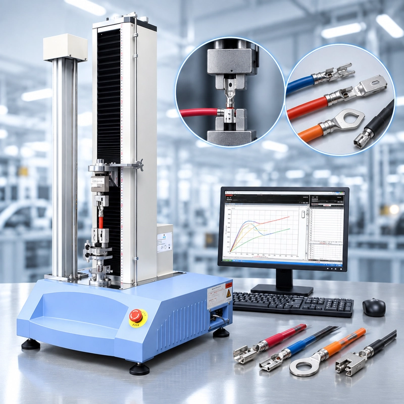
An automotive harness supplier needs one pull-force station for 0.35 mm² signal wires, 2.5 mm² power circuits and a dozen terminal families. Quality control expects roughly 400 tests a day.
At first, this sounds like a simple tensile-machine request.
Maximum force is easy to check. The harder questions are what happens around the machine: how many terminal geometries operators need to load, where their normal pull forces actually fall, whether specimens are positioned consistently between operators, and how quickly the station can move from one terminal family to another without adding test variation.
That is why an automotive wire harness pull test should not be planned around a single number such as "500 N required."
It should be planned around the harness program and its QC workflow.
Automotive Harness Pull Force Is Not One Test
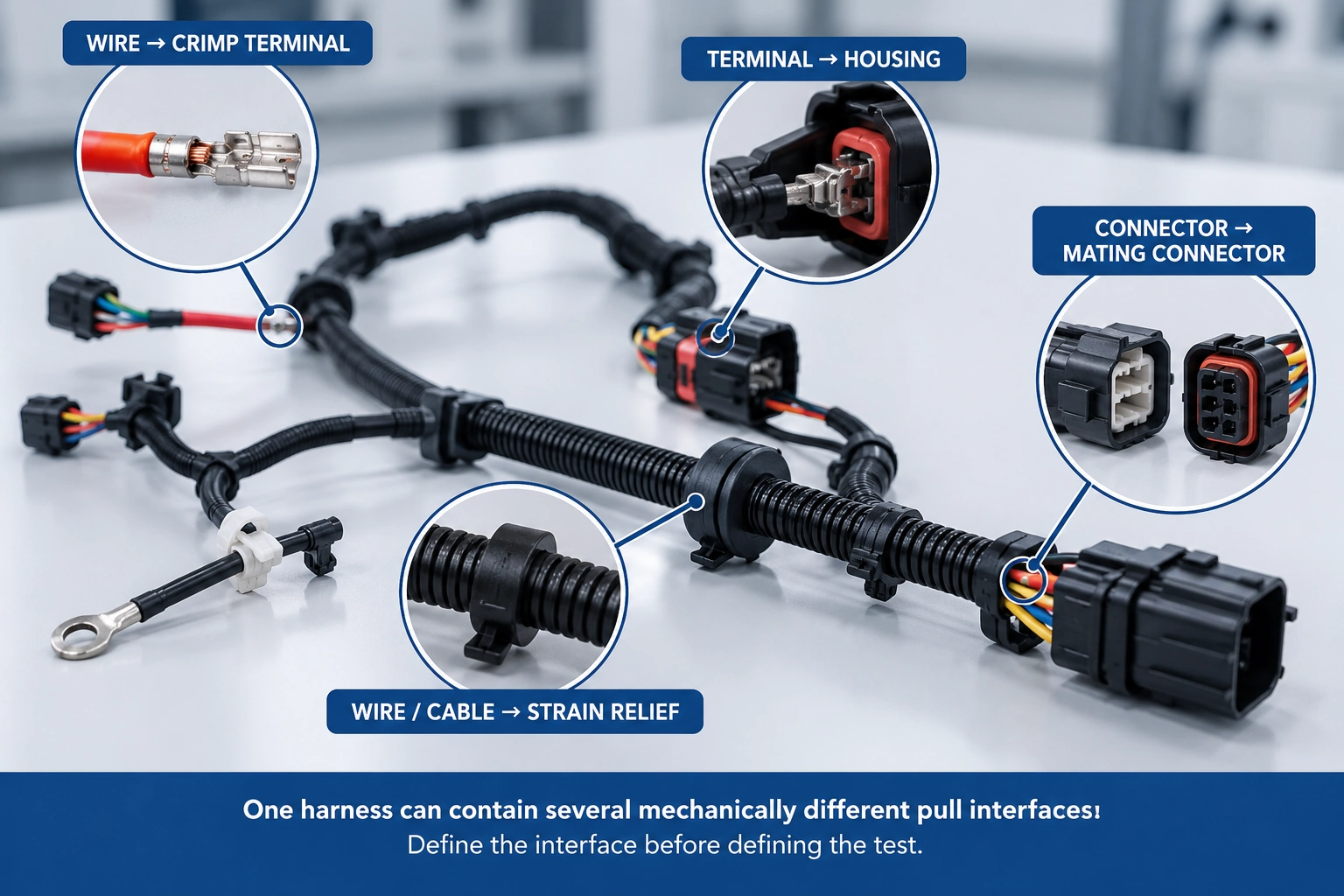
A finished wiring harness contains several mechanical interfaces that can be pulled.
The conductor is crimped to a terminal. The terminal is retained in a connector housing. A wire or cable may pass through a strain-relief feature. Two connector halves may also have defined mating or unmating requirements.
All of these may be described informally as a "pull test," but mechanically they are different.
| Test Interface | What Is Being Evaluated? | Main Setup Consideration |
|---|---|---|
| Wire → crimp terminal | Mechanical integrity of the crimped connection | Restrain terminal and grip conductor |
| Terminal → housing | Contact retention | Support housing and access the contact |
| Wire/cable → strain relief | Assembly pull-out resistance | Support connector or assembly correctly |
| Connector → connector | Separation / unmating behavior | Hold both connector halves on the intended axis |
For automotive harness production, conductor-to-terminal pull testing is a common QC application. This article concentrates on that production environment rather than treating every connector pull test as the same procedure.
If the requirement concerns the mechanics of an individual conductor-to-terminal connection, our Crimp Pull Test Guide looks more closely at crimp fixtures, working-force range and failure behavior.
Start With the Program Requirement, Not a Generic Force Table
One of the easiest mistakes in harness QC is starting with a search for a universal force value.
A quality engineer enters:
0.5 mm² wire pull force requirement
and quickly finds tables containing minimum values.
The number may look useful. That does not mean it belongs in the control plan for the harness being manufactured.
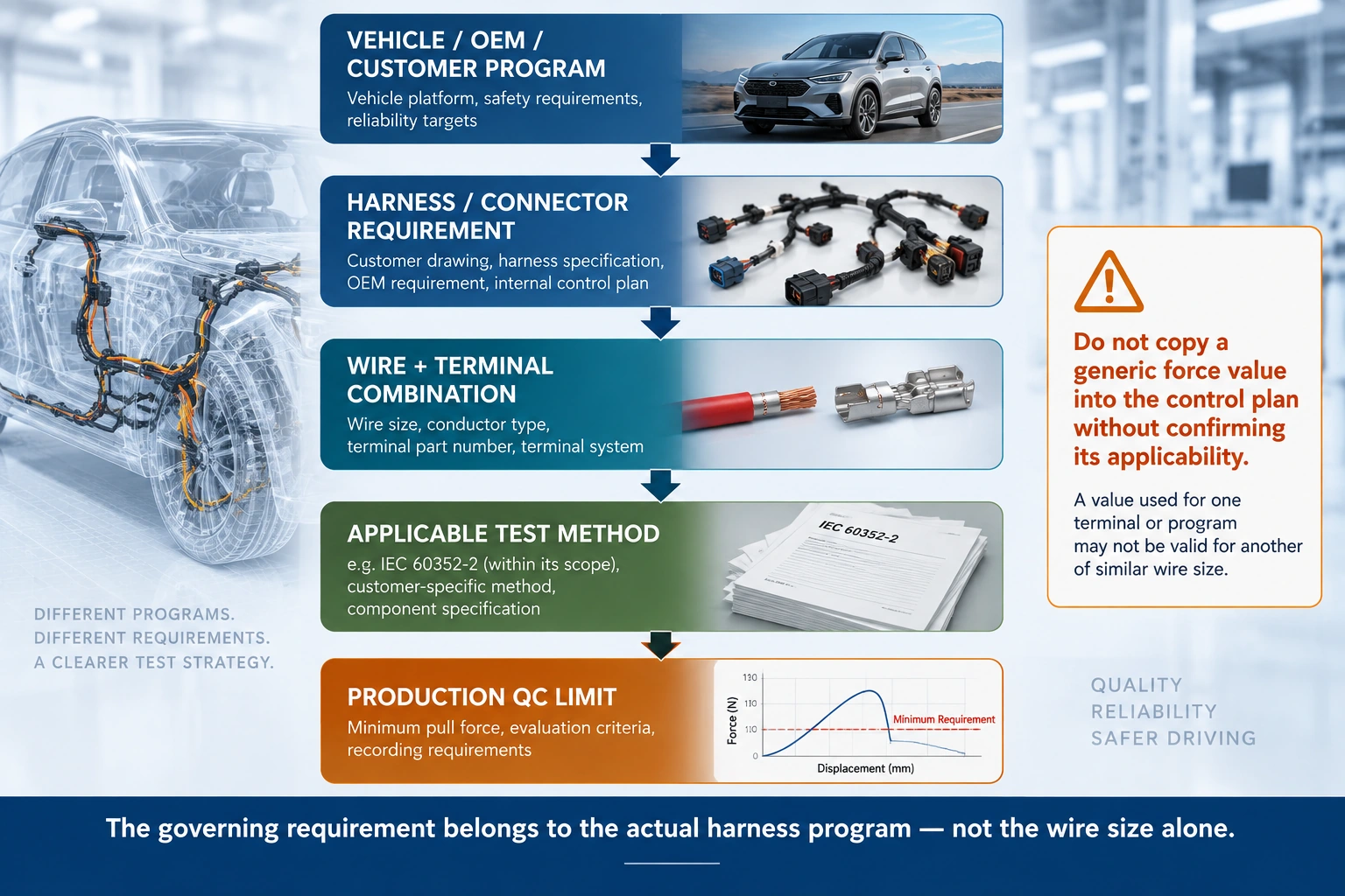
An automotive program can be governed by a customer or OEM requirement, terminal-system specification, harness drawing, internal control plan or an applicable component test method. A requirement used for one terminal family should not automatically be transferred to another because the conductor cross-section happens to be similar.
IEC 60352-2, for example, addresses solderless crimped connections within its defined scope. Automotive programs may also use customer-, OEM- or industry-specific requirements. The governing document must therefore be confirmed for the actual connection being tested.
There is a practical distinction worth keeping clear:
The test method defines how the specimen is tested. The product requirement defines what that connection needs to achieve.
They may not come from the same document.
Before configuring a pull-force station, establish the chain:
Vehicle / Customer Program → Harness or Connector Requirement → Wire + Terminal Combination → Applicable Test Method → QC Limit
That is safer than starting with a generic wire-size-versus-force table and working backward.
A Passing Result Can Still Hide Process Drift
A pull test is often treated as a simple decision:
PASS / FAIL
That decision is necessary, but a sequence of production results can tell a second story.
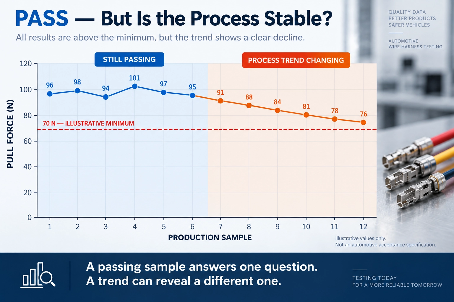
Consider a terminal family that normally produces results such as:
96 / 98 / 94 / 101 / 97 / 95 N
Later, the same process begins returning:
91 / 88 / 84 / 81 / 78 / 76 N
Assume, purely for illustration, that the specified minimum is 70 N.
Every specimen still passes.
The trend is nevertheless difficult to ignore.
A quality engineer now has a reason to investigate the process before waiting for the first specimen to cross the rejection limit.
The pull test cannot identify the root cause by itself. It does not know whether the change came from crimp height, strip length, conductor position, damaged strands, terminal feed, tooling condition or material variation.
What it can show is that the mechanical output of the process has moved.
A single result answers:
Did this specimen satisfy the requirement?
A sequence of results can raise another question:
Is this process still behaving the way it normally does?
For an automotive harness line producing large numbers of crimped connections, that second question can be just as valuable as the individual pass/fail decision.
Pull Force Makes More Sense When Read With the Crimp Process
Pull force should not be expected to explain everything about crimp quality.
It is a destructive mechanical check. It tells the engineer how the finished connection behaved when loaded, but it does not directly explain why the connection behaved that way.
Suppose average pull force declines over several production lots. The next investigation may include crimp height, strip length, conductor position, strand condition, terminal positioning and tooling condition.
Conversely, one dimensional process check can remain within its control limits while a mechanical trend begins to move.
Neither observation automatically replaces the other.
This is why production pull-force data becomes more useful when it can be interpreted alongside relevant crimp-process information. A stable control plan may combine mechanical testing with dimensional, visual and process checks appropriate to the harness program.
The pull test is one window into the process, not the entire process itself.
That is also a reason to retain meaningful test records rather than reducing every measurement to a green PASS indicator.
One QC Station, Many Terminal Families
A development laboratory testing one terminal can optimize everything around that terminal.
A harness plant has a different problem.
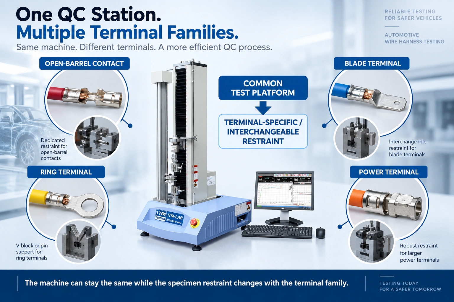
The same QC station may receive small open-barrel contacts in the morning, ring terminals later in the shift and larger power connections from another harness program.
The tensile frame does not necessarily need to change.
The terminal restraint often does.
A ring terminal may be located using an appropriate pin. A small contact may require a slotted restraint. A blade terminal needs a holder that suits its geometry. Larger connections may require a different restraint and a different useful force range.
Twelve terminal families do not automatically mean twelve completely independent fixture assemblies.
During fixture planning, similar terminal geometries can be reviewed to determine whether they can share a fixture body, restraint concept or interchangeable insert. The objective is not to force every product into a "universal" fixture. It is to avoid unnecessary changeover while locating each terminal repeatably.
This changes the equipment question from:
Which machine can pull this terminal?
to:
How many terminal families must this station support, and how quickly can operators move between them without changing the test condition?
For a development bench, a few extra seconds of fixture adjustment may not matter.
At several hundred specimens per day, they do.
Why Operator Setup Changes the Result
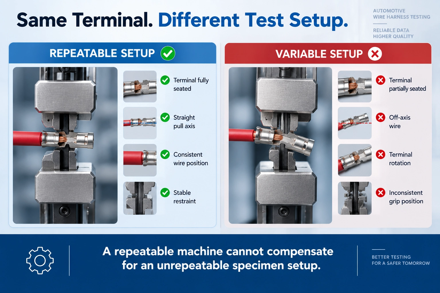
Operator A seats the terminal fully against the fixture stop.
Operator B leaves the next specimen slightly forward.
One wire runs vertically into the grip. Another enters at a small angle. One operator leaves a consistent free length; another grips closer to the terminal whenever the available wire is short.
None of these differences looks dramatic on the shop floor.
Together, they can widen the scatter in the test data.
Repeatability is therefore partly a property of the force-measuring system and partly a property of specimen loading.
The terminal should be restrained without introducing an unintended bending condition. The conductor should follow the intended pull axis. The wire grip needs enough holding force to prevent slip without creating a premature failure at the jaw.
For repetitive production testing, the fixture should also help the operator find the intended position rather than relying entirely on experience.
That may mean a positive seating position, an appropriate slot or insert, easier access around the terminal, or a repeatable way to establish the free wire length.
When an unexpectedly low value appears, the specimen deserves a look before anyone starts adjusting the crimping process.
Did the conductor pull from the terminal? Did the wire break? Did it move inside the grip? Did the terminal rotate? Was the pull visibly off-axis?
A value produced by grip slip is a test-setup problem, not evidence of a weak production crimp.
One Test Station May Have More Than One Useful Force Range
Machine capacity answers one question:
Can the frame apply enough force?
It does not completely answer another:
Is this the right measurement configuration for everything we test?
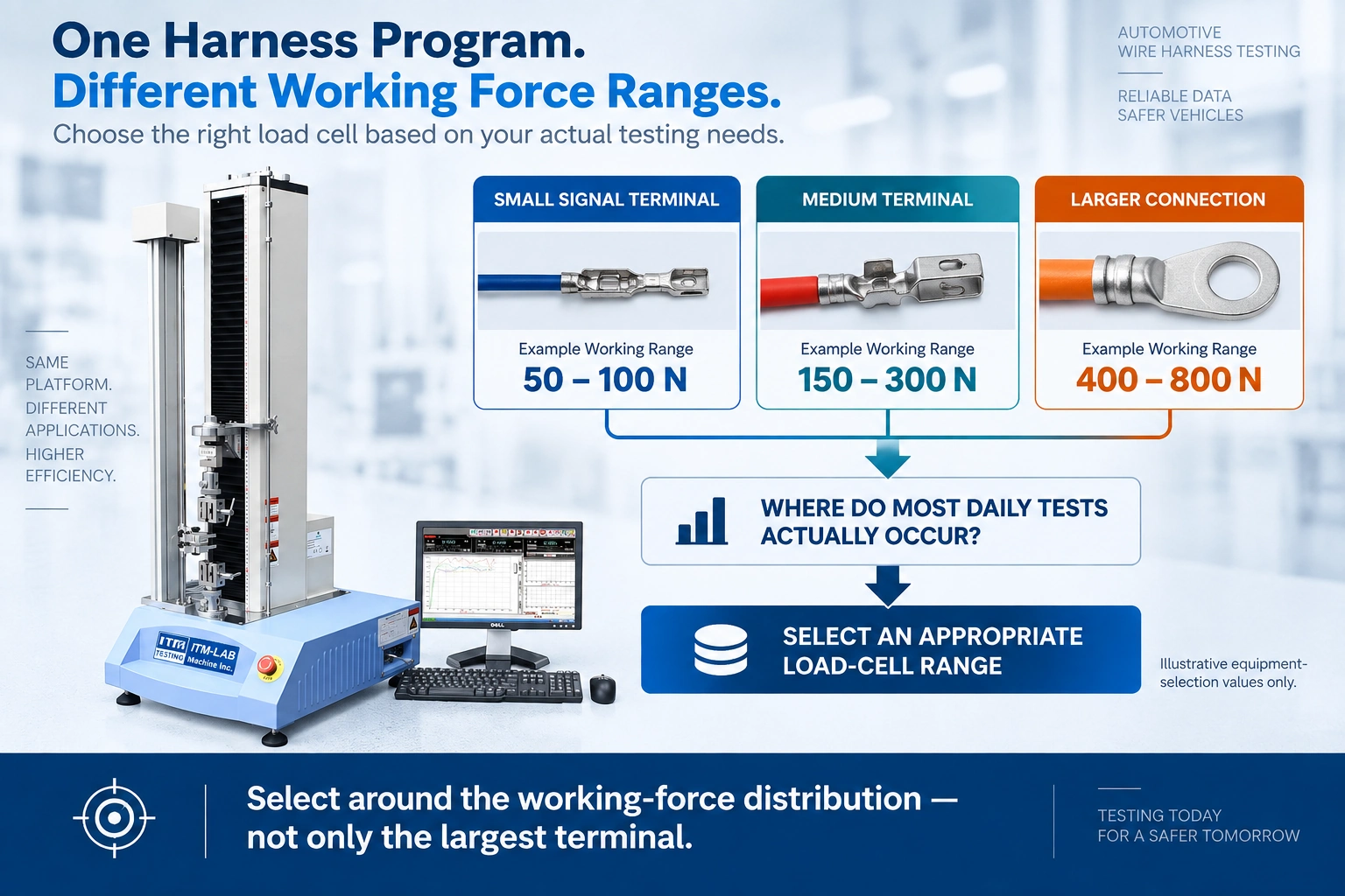
Consider a harness laboratory covering several connection families. For equipment-planning purposes only, imagine the following working ranges:
| Product Group | Illustrative Expected Working Force |
|---|---|
| Small signal terminals | 50–100 N |
| Medium terminal family | 150–300 N |
| Larger connection | 400–800 N |
These are illustrative equipment-selection values, not automotive acceptance requirements.
Suppose most daily samples fall below 150 N while a much smaller group operates several times higher.
Selecting the measurement system solely around the largest specimen can overlook where most of the machine's working day is actually spent.
A better discussion includes the lowest force of interest, the normal working range for each terminal family, the highest expected actual force and the number of tests performed in each range.
Depending on that spread, the laboratory can evaluate whether one load-cell configuration is suitable or whether different measurement ranges should be considered.
The useful input here is the expected actual working force, not merely the minimum pass value printed on a drawing.
At 500 Tests per Day, Specimen Handling Becomes Part of the Specification
A test station used twenty times a day can tolerate a few awkward steps.
At five hundred tests per day, those same steps become production time.
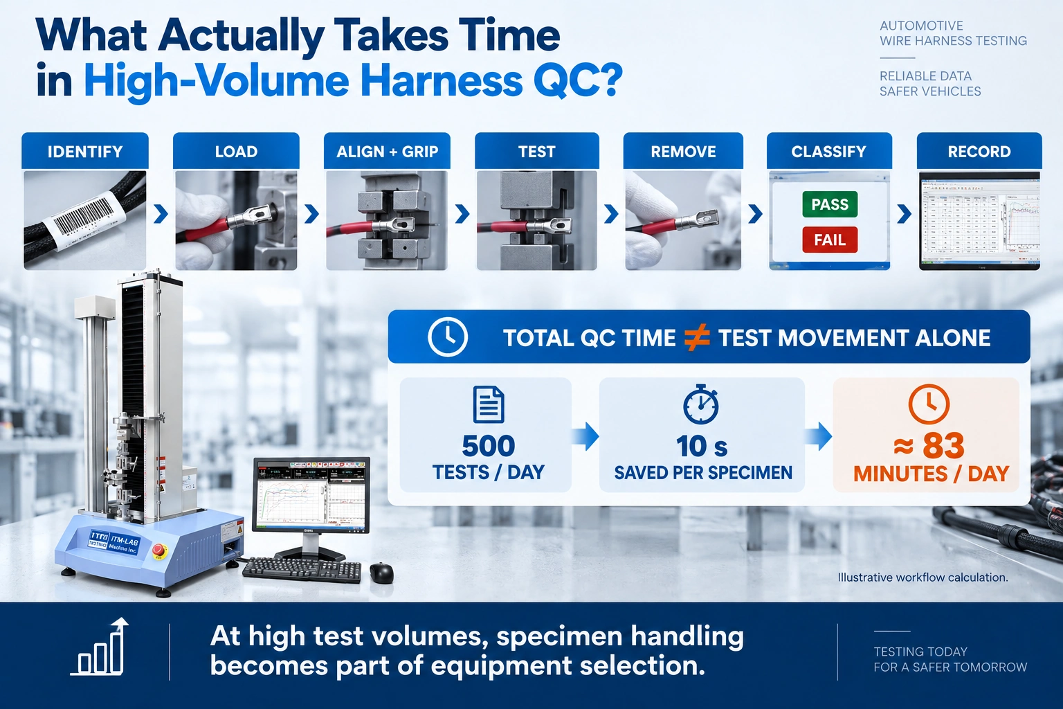
A complete cycle includes more than crosshead movement:
Identify specimen → Load terminal → Grip and align wire → Run test → Remove specimen → Classify result → Record data
Imagine that loading and positioning require 30 seconds per specimen.
Across 500 tests, that alone represents more than four hours of handling.
Reduce the process by only 10 seconds per specimen and roughly 83 minutes disappear from the daily workload.
That is why simply increasing test speed is not always the most effective way to increase throughput.
In high-volume harness QC, practical gains may come from easier terminal access, faster fixture changeover, repeatable positioning, convenient grip operation and less manual result handling.
The best production setup is not necessarily the one that moves fastest.
It is the one that removes unnecessary work from the entire test cycle without compromising the test condition.
Configuring the RS-8010A for Automotive Harness QC
For many automotive wire-harness pull applications, the forces involved are relatively low compared with structural tensile testing.
The ITM-LAB RS-8010A Servo Control Universal Testing Machine, available in capacities from 50 N to 5 kN, is therefore a platform to evaluate for many terminal and harness pull-force applications.
Specifying the machine model alone, however, does not define the test system.
For a conductor-to-terminal application, the configuration may combine an appropriate load cell with a wire grip and a restraint matched to the terminal geometry. Available test space and travel also need to suit the specimen.
Where several terminal families share the same station, fixture access and changeover should be considered at the same time as force range.
Required data can vary as well.
A production station may primarily need peak force and pass/fail information. Development, process validation or troubleshooting work may benefit from retaining the force-displacement curve and observed failure behavior.
For example:
Terminal A — 96 N — PASS — conductor pull-out
contains more diagnostic information than:
Terminal A — PASS
That does not mean every harness line needs a complex data system. It means the required output should be defined before the station is configured.
For a low-force harness QC station, the RS-8010A can be evaluated together with the appropriate load cell, wire grip, terminal restraint and test method. For multi-terminal programs, fixture changeover and operator workflow should be considered as part of the same configuration rather than after the machine has already been selected.
A Real Automotive Harness RFQ
Consider this request:
| Requirement | Customer Information |
|---|---|
| Application | Automotive wire harness production QC |
| Wire Sizes | 0.35 / 0.5 / 0.75 / 1.5 / 2.5 mm² |
| Terminal Families | 12 |
| Daily Test Volume | 350–500 specimens |
| Required Output | Peak force + pass/fail |
| Requirement | Customer specification |
| Preferred Setup | One test station |
There is enough information to understand the application.
There is not yet enough to configure the station properly.
The next useful document is often not another machine specification.
It is the terminal list.
| Terminal PN | Wire Size | Minimum Requirement | Expected Working Force | Tests / Day | Drawing / Sample |
|---|---|---|---|---|---|
| T-001 | 0.35 mm² | Customer Spec | To confirm | 120 | Available |
| T-002 | 0.50 mm² | Customer Spec | To confirm | 180 | Available |
| T-003 | 1.50 mm² | Customer Spec | To confirm | 80 | Available |
| T-004 | 2.50 mm² | Customer Spec | To confirm | 40 | Available |
Now the equipment discussion becomes much more concrete.
If most terminal families share similar low-force behavior while only a few require substantially higher forces, the load-cell strategy can be evaluated around that distribution.
If several terminals share similar geometry, the restraint strategy can be reviewed for common components or interchangeable inserts.
And if the station is expected to process 500 specimens a day, loading, fixture changeover and data handling become measurable parts of the project.
That is the information needed to move from a generic pull tester to a useful production test station.
What to Send Before Requesting a Harness Pull-Force System
For a new automotive harness project, provide the information that defines the production application rather than only the maximum machine capacity.
The most useful inputs are:
- wire sizes and conductor types;
- terminal part numbers;
- terminal drawings or finished samples;
- applicable customer/OEM/product requirement;
- applicable test method;
- minimum specified force;
- expected actual working-force range;
- required test speed;
- number of terminal families;
- approximate tests per day;
- required test output and traceability.
If several terminals will share the station, a spreadsheet listing terminal part number, wire size, specified minimum, expected working force and daily quantity is especially useful.
Physical terminals or finished crimp samples are valuable when evaluating the restraint. Fixture geometry cannot be determined reliably from a force value alone.
Automotive Wire Harness Pull Force Test System Selection Roadmap
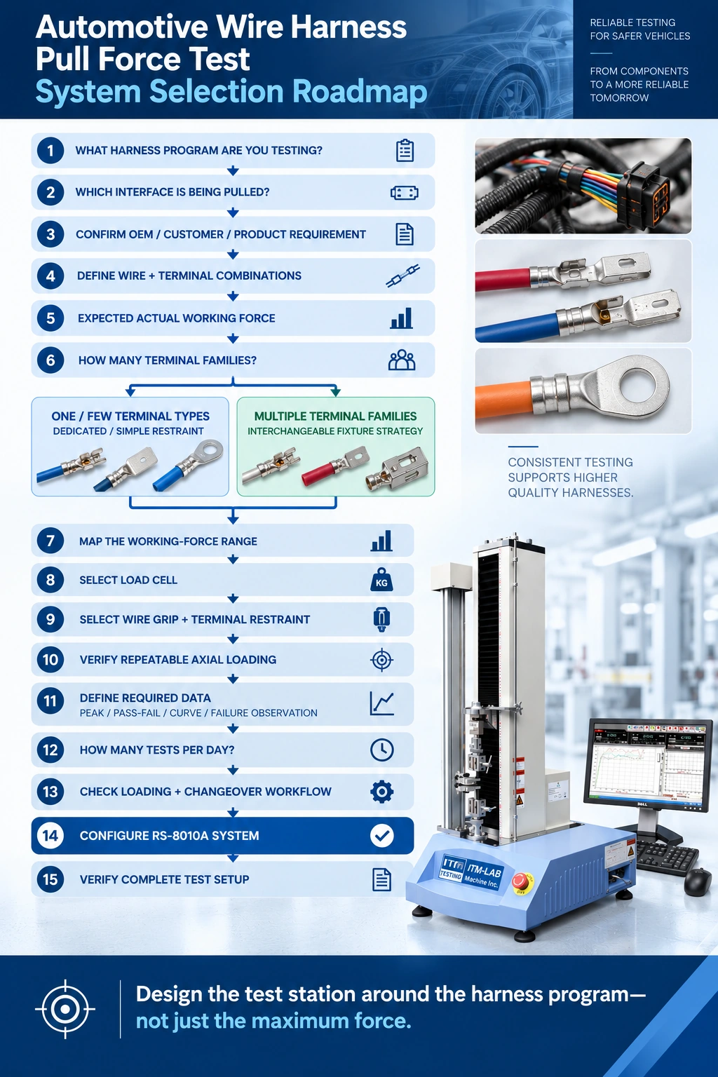
Automotive Wire Harness Pull Force Testing FAQ
What pull-force tests are used for automotive wire harnesses?
"Pull force" can refer to several mechanical interfaces, including conductor-to-terminal crimp strength, terminal retention in a connector housing and strain-relief or assembly pull-out testing. Connector mating or unmating force is another mechanically different measurement.
The interface should therefore be identified before selecting the fixture or test procedure.
Is a wire harness pull test the same as a crimp pull test?
Not necessarily.
A crimp pull test specifically loads the conductor-to-terminal connection. Wire harness pull testing is a broader description and can include other mechanical interfaces within the assembly.
For production crimp QC, the conductor-to-terminal connection is typically the interface of interest.
How much pull force should an automotive terminal withstand?
There is no single force value that applies to every automotive terminal of a given wire size.
The acceptance requirement should come from the specification governing the actual conductor, terminal and harness program. A generic online force table should not be substituted for that requirement without confirming its applicability.
Can pull force be used to monitor crimp quality?
Yes, pull-force data can provide useful mechanical QC information and may reveal changes in process behavior over time.
It does not identify the root cause of a change by itself. Unexpected trends may need to be investigated alongside crimp height, conductor position, strand condition, terminal positioning, tooling condition and other relevant process information.
Why do different operators sometimes get different pull-force results?
Differences in terminal seating, wire-grip position, free specimen length, terminal rotation and pull-axis alignment can introduce variation.
A production fixture should make the intended specimen position as repeatable as practical so the result depends less on individual operator technique.
How should I choose a load cell for automotive harness pull testing?
Start with the expected actual working-force range rather than only the minimum acceptance value or maximum frame capacity.
For a station covering several terminal families, map the expected force range and daily quantity for each family. This helps determine where most measurements occur and whether one load-cell range is appropriate for the entire program.
What information is needed to select an automotive wire harness pull test machine?
Provide the wire sizes, conductor types, terminal part numbers or drawings, applicable test requirement, specified minimum forces, expected actual force ranges, test speed, number of terminal families and daily sample volume.
Finished crimp samples are particularly useful when the terminal fixture needs to be evaluated.
Building a Better Harness QC Station
The easiest part of an automotive wire harness pull-test project is often confirming that the tensile frame has enough capacity.
The production details determine whether the station will still work well after hundreds of specimens, multiple terminal changes and several operators.
A useful system needs to accommodate the terminal families actually being manufactured, measure where their real pull forces occur, hold specimens consistently and move through the required sample volume without turning specimen loading into the bottleneck.
The resulting data should also be useful. A single PASS result verifies one specimen. A changing pull-force trend can give the quality team an earlier reason to inspect the production process.
For many lower-force automotive terminal applications, the ITM-LAB RS-8010A, available from 50 N to 5 kN, can serve as the test platform. The final configuration still depends on the load cell, wire grip, terminal restraint, available test space, applicable test method and production workflow.
If you are planning an automotive harness QC station, send ITM-LAB your terminal list, wire-size range, terminal drawings or finished samples, governing requirements, expected pull-force ranges and tests per day.
With those details, ITM-LAB can evaluate the load-cell range, wire grip, terminal restraint and RS-8010A configuration around the actual harness program.
