
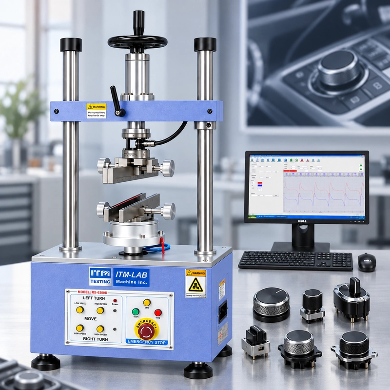
Two HVAC knobs can both record a peak torque of 0.42 N·m and still behave noticeably differently.
One may break away cleanly, rotate with steady resistance, and produce four well-defined detents. The other may feel heavy at the start, light through the middle, and unusually sharp at one position.
If the test report contains only:
Peak Torque: 0.42 N·m
that difference disappears.
This is the challenge with automotive knob torque testing. A rotary control is not always defined by one maximum value. What happens before that maximum, where it occurs in the rotation, and what happens afterward can be just as important.
For a rotary switch, selector, or encoder, the useful measurement may therefore be a complete mechanical event:
initial movement → running resistance → detent transitions → continued rotation → reverse movement
When torque is recorded together with rotational angle, those events become much easier to separate and compare.
This guide explains how to test automotive knobs and rotary switches, how to interpret torque-angle data, where misleading results come from, and what information is needed to configure the right torque test system.
What Are You Actually Measuring?
A knob torque test sounds straightforward: hold the component, rotate the control, and measure torque.
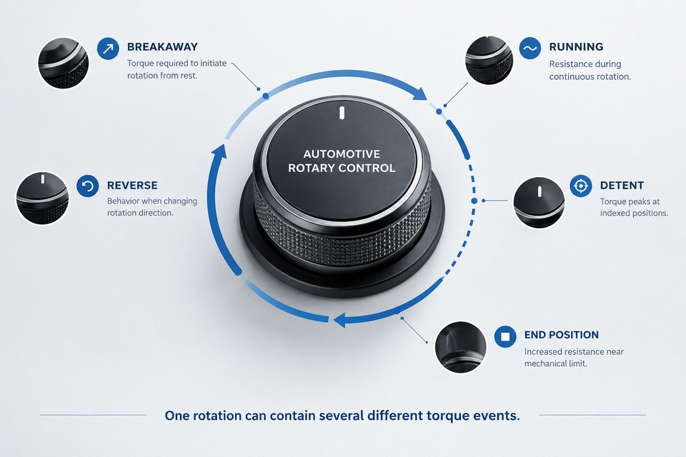
The problem is that "torque" can refer to several different parts of the same movement.
Consider a five-position HVAC selector.
At the beginning of the test, the mechanism is stationary. The first measurable event may be the torque required to overcome static resistance and initiate movement.
Once moving, the selector enters its normal rotational region.
As it travels from one setting to another, the internal detent mechanism creates a sequence of peaks and valleys. Each of those events occurs at a particular angular position.
Reverse the direction, and the pattern may change again.
A useful test therefore starts by defining the event rather than simply asking for a maximum N·m value.
| Measurement | What It Helps Describe |
|---|---|
| Breakaway Torque | Torque required to initiate rotation |
| Running Torque | Resistance during continued rotation |
| Detent Torque | Torque behavior around indexed positions |
| Peak Torque | Highest torque within the defined event |
| Angular Position | Where a torque event occurs in the rotation |
| CW / CCW Torque | Direction-dependent rotational behavior |
| Torque vs. Angle | How torque develops through the complete movement |
Not every control requires every measurement.
A continuously rotating encoder may have no mechanical detents. A three-position selector may be defined primarily by indexed transitions. Another component may only need operating torque within a specified angular window.
The test should follow the mechanism.
Peak Torque Can Hide the Difference
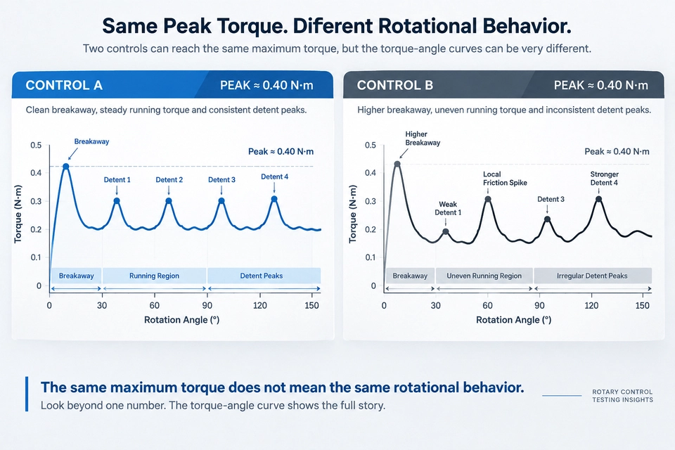
Suppose two rotary controls are tested over the same angle and at the same rotational speed.
Both produce:
Peak Torque ≈ 0.40 N·m
If that is the only recorded result, they look equivalent.
Now look at the curves.
Control A has a modest breakaway event followed by four evenly spaced, similarly shaped detent peaks.
Control B reaches almost the same maximum value, but its first detent is weak, the second is sharp, and a local friction increase appears between positions three and four.
Same peak. Different rotational behavior.
This is why peak torque is useful, but it should not automatically become the entire test.
For indexed controls in particular, engineers may need to know not only how high the torque became, but also where it happened and how the surrounding curve behaved.
How to Read a Knob Torque-Angle Curve
A torque-angle curve connects two pieces of information:
How much torque?
and:
At what rotational position?
The vertical axis represents torque.
The horizontal axis represents rotation angle.
For a five-position selector, a simplified event might look like:
0° → Detent 1 → 30° → Detent 2 → 60° → Detent 3 → 90° → Detent 4 → 120°
The exact pattern depends on the mechanism, but several regions are commonly worth examining.
Initial Breakaway
The first peak may occur as the control starts moving from rest.
This can be influenced by static friction, lubrication, spring loading, seals, and contact between internal parts.
A control can have relatively low running torque but still require noticeably more torque to initiate movement.
That difference is easy to miss if the test only reports an average value.
Running Region
Between discrete events, the curve shows the resistance required to continue rotating the mechanism.
This region does not have to be perfectly flat.
What matters is whether its behavior matches the product requirement and whether unexpected changes are repeatable.
A local increase might deserve investigation. So might a gradual rise, sudden drop, or direction-dependent difference.
The curve shows that something changed.
It does not, by itself, prove why.
Detent Events
An indexed rotary switch typically produces a recognizable torque pattern as it moves through each position.
Instead of treating the entire test as one peak, engineers can compare individual detents.
For example:
Detent 1: 0.31 N·m
Detent 2: 0.33 N·m
Detent 3: 0.32 N·m
Detent 4: 0.44 N·m
The fourth position is immediately more interesting than it would be in a report containing only:
Maximum Torque = 0.44 N·m
The curve provides context.
The maximum tells you how much. Torque-angle data helps show where it happened.
Detent Position Can Matter as Much as Detent Torque
For an indexed control, another question is often overlooked:
Where does the detent occur?
Imagine a design with nominal detent positions at:
30° / 60° / 90° / 120°
A test might produce:
| Position | Nominal Angle | Measured Event |
|---|---|---|
| Detent 1 | 30° | 30.4° |
| Detent 2 | 60° | 60.1° |
| Detent 3 | 90° | 91.2° |
| Detent 4 | 120° | 120.3° |
These numbers are illustrative, not acceptance limits.
The point is that torque magnitude alone would not reveal the positional shift at Detent 3.
For some controls, that may not matter. For others, angular position is part of the functional requirement.
This is one reason torque and angle are particularly useful when evaluated together.
For an indexed control, the question may be not only "How strong is the detent?" but also "Where does it occur?"
Clockwise and Counterclockwise Are Separate Test Conditions
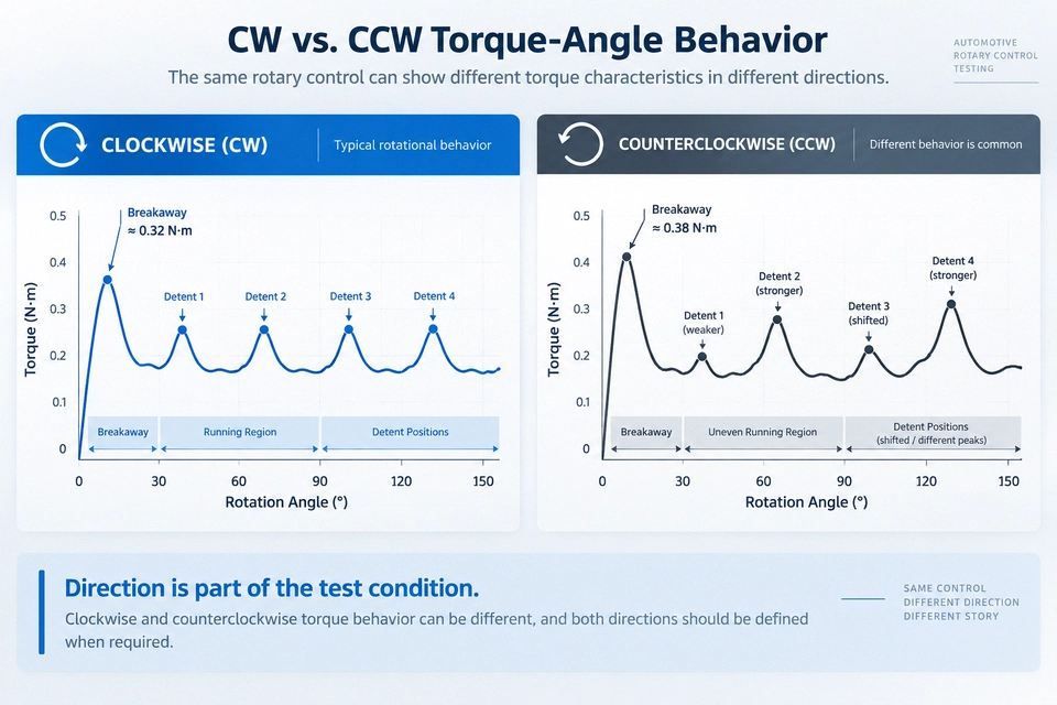
A rotary mechanism does not necessarily behave identically in both directions.
Internal cam geometry, spring loading, lubrication, friction interfaces, and assembly tolerances can create different torque responses when the control is reversed.
For example, a selector might produce:
CW Breakaway: 0.32 N·m
CCW Breakaway: 0.38 N·m
The maximum values might also be similar while individual detent shapes or angular positions differ.
Neither result is automatically wrong.
The important point is that direction should be defined.
If the requirement covers both directions, the test method should not record clockwise rotation and assume counterclockwise behavior will be identical.
Torque-Angle Data Quantifies Part of "Feel"—Not All of It
Automotive interior controls are often evaluated in terms such as smooth, heavy, light, crisp, soft, or well-defined.
These descriptions matter because a driver interacts with the control directly.
Torque-angle testing can convert part of that experience into repeatable mechanical data.
A strong detent may appear as a larger torque event. Uneven detents may appear as inconsistent peaks. Excessive breakaway may be visible at the start of the curve.
But a torque curve should not be treated as a complete model of human perception.
Rotational feel may also be influenced by knob geometry, surface texture, axial or radial play, sound, temperature, and the way the user interacts with the control.
The more defensible engineering statement is:
Torque-angle measurement helps quantify rotational mechanical behavior. It does not replace every tactile or human-factor evaluation.
That distinction is especially useful when comparing prototypes.
A subjective comment such as:
"Sample B feels less consistent."
can be investigated against measured breakaway, detent, and running-torque behavior.
The measurement does not replace the observation. It helps investigate it.
One Good Curve Is Not a Process
A clean torque-angle curve from one sample can be useful.
It does not establish repeatability.
Suppose one rotary switch is tested repeatedly and most detent peaks fall around:
0.30–0.33 N·m
but one cycle produces:
0.44 N·m
That event deserves attention.
Was it the product? Fixture movement? A different starting condition? A local mechanical event?
Now suppose five different samples all show an increase around the same angular position.
That tells a different story.
For development and validation work, it can therefore be useful to distinguish within-sample repeatability from sample-to-sample variation.
This does not require turning every knob test into a statistical study.
It simply means the test method needs to be repeatable before small product differences are interpreted as meaningful.
A single curve describes one event. A repeatable test method tells you whether that event represents the product.
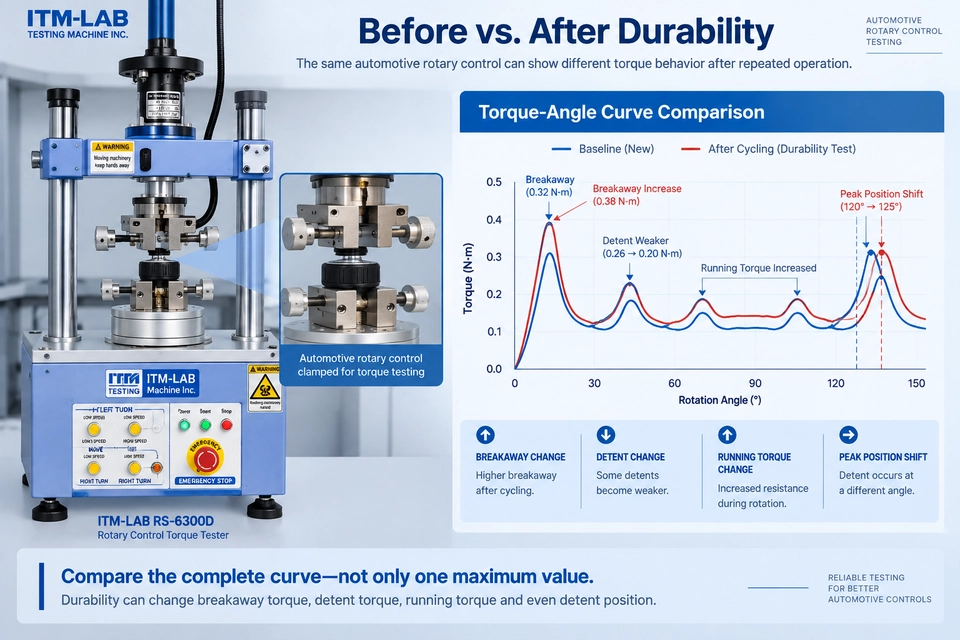
What Changes After Durability Cycling?
A new control is only one point in its life.
Repeated operation can change contact surfaces, lubrication distribution, springs, clearances, detent geometry, and other mechanical interfaces.
A practical comparison can therefore use the same controlled torque test before and after durability cycling:
BASELINE → DURABILITY CYCLING → POST-DURABILITY TEST → COMPARE
The useful comparison may include more than one peak value:
- Breakaway torque
- Running torque
- Individual detent peaks
- Detent angular positions
- CW / CCW difference
- Overall curve shape
Suppose maximum torque changes only from:
0.42 N·m → 0.40 N·m
That looks minor.
But the post-durability curve may show that two detents have become noticeably weaker while running resistance has increased elsewhere.
Looking only at the maximum would miss both changes.
Possible contributors could include wear, lubricant redistribution, spring relaxation, interface loosening, or material deformation. The torque curve alone should not be used to assign the root cause, but it can show where further investigation is needed.
Durability does not only change how much torque is required. It can change where and how that torque develops.
"Conditioned At" and "Measured At" Are Not the Same Thing
Automotive controls may be evaluated after low- or high-temperature exposure because temperature can change the behavior of materials and interfaces inside the mechanism.
Depending on the product, temperature can influence lubricant response, polymer stiffness, seals, springs, dimensional fit, and friction.
There is no universal direction of change.
It would be too simplistic to say that every knob becomes harder to rotate when cold or easier when hot. The actual product has to be measured.
There is also an important procedural distinction:
Conditioned at −20°C
does not necessarily mean:
Measured at −20°C
If a sample is removed from an environmental chamber and transferred to a room-temperature torque tester, its temperature begins changing immediately.
For a temperature-sensitive mechanism, transfer time may influence the result.
A test method should therefore define whether torque is measured during temperature exposure or after conditioning within a specified transfer/recovery condition, depending on the applicable requirement and available test setup.
"Conditioned at" and "measured at" are not interchangeable test conditions.
This small procedural detail can create a significant difference when laboratories try to compare results.
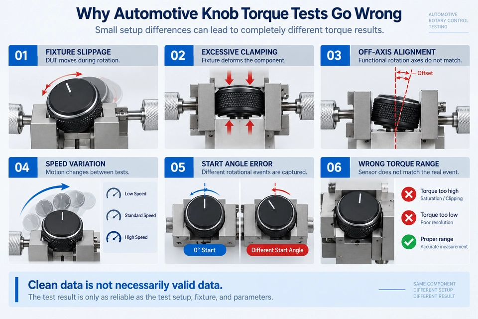
Why Automotive Knob Torque Tests Go Wrong
Modern sensors can produce very clean numerical data.
That does not guarantee that the data represents the intended mechanical event.
Six setup problems deserve particular attention.
1. Fixture Slippage
If the knob or DUT moves inside the fixture, some of the commanded rotation is lost in the setup.
The software may still generate a smooth curve, but that curve is not necessarily valid.
2. Excessive Clamping
The opposite mistake is gripping too aggressively.
A plastic knob, housing, or switch body can deform under clamping pressure, changing friction or alignment before the test starts.
The fixture should restrain the DUT without changing the mechanism being measured.
3. Off-Axis Alignment
This is especially important with irregular automotive controls.
The outside shape of a knob may not provide a reliable alignment reference.
Alignment should be established from the DUT's functional rotation axis—for example, the shaft axis, rotational center, or defined mounting datum—rather than simply making the external housing look visually centered.
Misalignment can introduce side load and additional resistance.
4. Inconsistent Rotational Speed
If speed changes between tests, the measured response may also change.
The test speed should therefore be defined and repeatable whenever the method requires controlled rotation.
5. Inconsistent Starting Angle
Starting at 0° on one sample and 5° on another may mean the two tests do not contain exactly the same mechanical events.
For indexed switches, the starting position and rotation window should be defined before comparing curves.
6. Wrong Torque Range
A sensor selected only from maximum capacity may be poorly matched to the working torque.
A sensor selected too close to the nominal torque can create the opposite problem if breakaway or transient peaks exceed the available range.
The sensor needs to cover the complete event while providing suitable measurement performance in the region that actually matters.
The Fixture Is Part of the Measurement
Automotive interior controls are rarely convenient laboratory shapes.
A test program may include round HVAC knobs, short selectors, recessed controls, rotary encoders, textured surfaces, irregular housings, or complete control modules.
There is no single fixture geometry that is automatically correct for all of them.
The rotating fixture needs to transmit torque without slipping or damaging the control.
The stationary fixture needs to restrain the DUT without distorting the housing or interfering with the mechanism.
And the rotational axes need to be aligned around the functional geometry of the component.
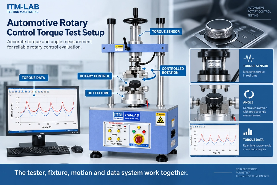
This makes the fixture part of the measurement chain:
Torque Sensor + Controlled Rotation + Rotary Fixture + DUT Fixture + Alignment + Angle Measurement + Data
If one of those elements is wrong, increasing sensor accuracy does not solve the problem.
A precise sensor can precisely measure the wrong setup.
Start With the Requirement, Not the Standard Number
There is no single universal torque specification that defines acceptable rotational behavior for every automotive knob, rotary switch, or selector.
Actual requirements may come from an OEM specification, Tier 1 requirement, component drawing, product validation plan, or internal test procedure.
That means equipment selection should start with the requirement itself.
What control is being tested? What movement is required? What torque event matters? At what angle? In which direction? At what speed? Under what environmental or durability condition? And what constitutes a pass or fail?
Once those questions are answered, the requirement can be translated into a measurement system.
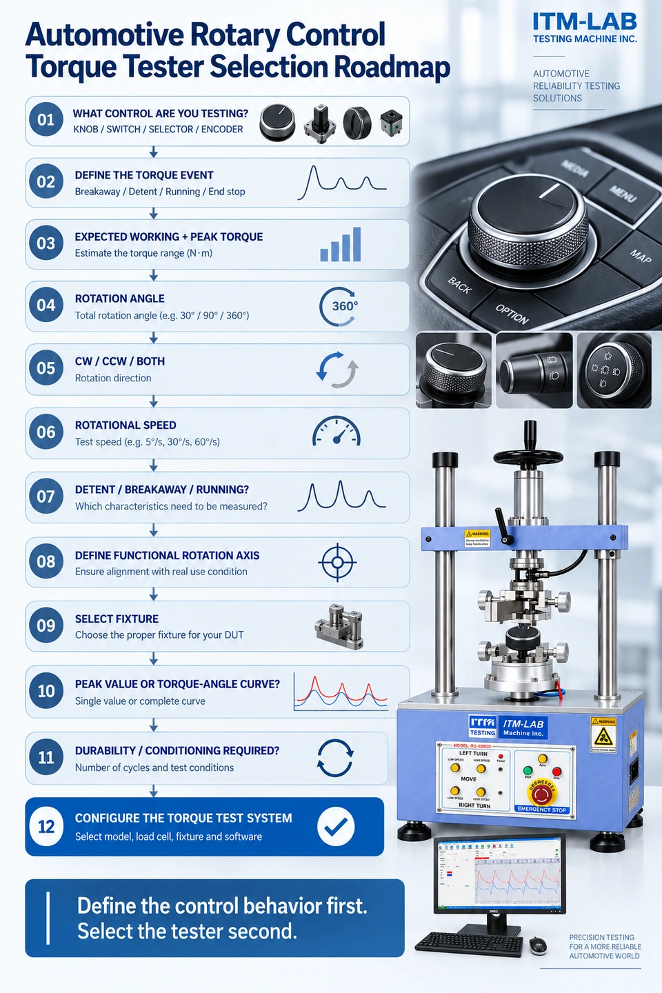
How to Select a Torque Tester for Automotive Rotary Controls
The selection process becomes much easier when the product is defined before the machine.
Start with the expected torque range, including the highest breakaway, detent, or transient event that needs to be captured. Do not size the sensor from normal running torque alone.
Then define the motion.
A three-position selector that moves through 60° is a different application from a continuous rotary encoder. The tester needs to reproduce the required angle, direction, and rotational speed.
Next comes the fixture.
A suitable torque range does not help if the DUT cannot be mounted around its functional rotation axis.
Finally, decide what data is actually required.
Some tests may need only:
Peak Torque
Others may need:
Breakaway + Running + Detent Peaks + Angular Position + Complete Torque-Angle Curve
For durability work, the system may also need repeatable cycling or consistent before/after measurement procedures.
The useful selection sequence is therefore:
DUT → Torque Event → Range → Angle → Direction → Speed → Fixture → Data → Test System
Define the control behavior first. Select the tester second.
What to Send When Requesting an Automotive Torque Testing Solution
Instead of sending:
"We need a knob torque tester."
send:
DUT: Knob / Rotary Switch / Selector / Encoder / Other
Application: HVAC / Infotainment / Lighting / Seat / Other
Normal Working Torque: _____ N·m
Highest Expected Torque: _____ N·m
Breakaway / Detent Peak: _____ N·m
Rotation Angle: _____ °
Rotation Direction: CW / CCW / Both
Rotational Speed: _____
Detent Positions: _____
Required Result: Peak / Breakaway / Running / Detent / Torque-Angle Curve
DUT Dimensions: _____
Functional Rotation Axis / Mounting Datum: _____
Fixture Requirement: _____ / Recommend
Durability Test Required: Yes / No
Environmental Conditioning: _____
Measured at Temperature: Yes / No / Not Defined
Test Specification / Drawing: _____
That information allows the supplier to evaluate:
Torque Range → Sensor → Motion → Angle → Fixture → Data → Machine
If the torque range is not yet known, send a product drawing, sample photograph, previous test curve, or representative sample information rather than guessing the machine capacity.
FAQ
What does a knob torque test measure?
A knob torque test measures rotational resistance under defined test conditions. Depending on the component, the result may include breakaway torque, running torque, detent torque, peak torque, and torque as a function of rotational angle.
What is detent torque in a rotary switch?
Detent torque describes the torque behavior associated with moving through an indexed position. For a multi-position switch, engineers may compare both the magnitude and angular position of individual detent events.
Why is a torque-angle curve useful?
A peak value tells you the maximum torque reached. A torque-angle curve also shows where that value occurred and what happened throughout the rest of the rotation. This is particularly useful for identifying breakaway behavior, detent patterns, and local changes in running resistance.
Should CW and CCW torque be tested separately?
If the requirement covers both directions, they should be defined and measured accordingly. Mechanical geometry and friction can produce different clockwise and counterclockwise behavior.
Can torque testing measure how a knob "feels"?
It can quantify important parts of rotational mechanical behavior, such as breakaway, running resistance, and detent consistency. It does not represent every aspect of human tactile perception, so it may be used alongside other product-specific evaluations.
How should I choose the torque range?
Use the complete expected event—not just normal running torque. Consider breakaway and detent peaks, product variation, and any other torque event the test must capture, then verify that the selected sensor provides suitable measurement performance within that range.
Can I compare torque before and after environmental conditioning?
Yes, if the procedure defines the conditions clearly. Pay particular attention to whether the DUT is measured at the conditioning temperature or after transfer, because those are not necessarily equivalent test conditions.
Final Thoughts
For an automotive rotary control, one peak value can be correct and still leave most of the mechanical story untold.
A useful test asks more specific questions.
How much torque starts the movement? What happens during rotation? Are the detents consistent? Where do they occur? Does the behavior change in the opposite direction? And does the same pattern remain after cycling or environmental exposure?
Torque-angle measurement provides a way to answer those questions with repeatable mechanical data.
But the curve is only as useful as the test behind it.
The torque range, rotation, speed, starting position, alignment, and fixture all need to represent the actual DUT.
That leads to the central principle for this application:
Same peak torque does not necessarily mean the same rotational behavior.
Define the control behavior first. Then build the measurement system around it.
Need to Configure an Automotive Rotary Control Torque Test?
Send ITM-LAB your DUT, expected working and peak torque, rotation angle, direction, speed, dimensions, fixture information, and required results.
These details can be used to evaluate the torque range, sensor, fixture, controlled motion, and torque-angle measurement requirements around the actual automotive control.
