
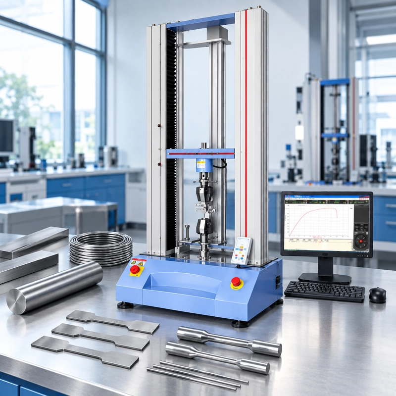
Two RFQs land on the same desk.
Both say:
We need a tensile testing machine for ISO 6892-1.
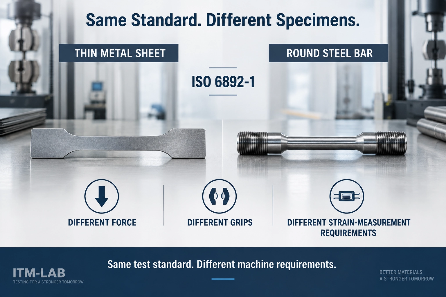
The first drawing shows a thin aluminum specimen.
The second shows a machined high-strength steel bar.
They should not automatically receive the same quotation.
The standard is the same. The forces may be completely different. So may the load cell, grips, extensometer, control method, and test workflow.
That is the distinction this guide is about.
ISO 6892-1 is a test-method requirement. It is not a machine specification.
If you are selecting equipment, the useful starting point is not the standard number alone. It is the specimen sitting—or soon to be sitting—on your laboratory bench.
ISO 6892-1 Is Not a Machine Specification
The current edition is ISO 6892-1:2019, Metallic materials — Tensile testing — Part 1: Method of test at room temperature. ISO reviewed and confirmed the edition in 2025, so it remains current. It specifies the method for tensile testing metallic materials and defines mechanical properties that can be determined at room temperature.
That defines the test.
It does not define one universal machine configuration.
A thin sheet specimen and a machined round bar can both fall within an ISO 6892-1 test program. But one might fail below 20 kN while another requires well over 100 kN.
Even when two specimens produce similar maximum forces, they may not use the same grips.
And if one laboratory only needs tensile strength while another needs proof strength with controlled strain rate, their measurement and control requirements change again.
So when an inquiry says:
ISO 6892-1 machine required.
we already know the standard.
What we still need is the test.
First Number We Need: Expected Force
Show us the specimen drawing and we can start turning the test requirement into a machine requirement.
For initial equipment sizing, a useful estimate is:
Expected Maximum Force ≈ Original Cross-Sectional Area × Expected Tensile Strength
This is not the ISO test procedure or an acceptance calculation. It is a practical first estimate for machine selection.
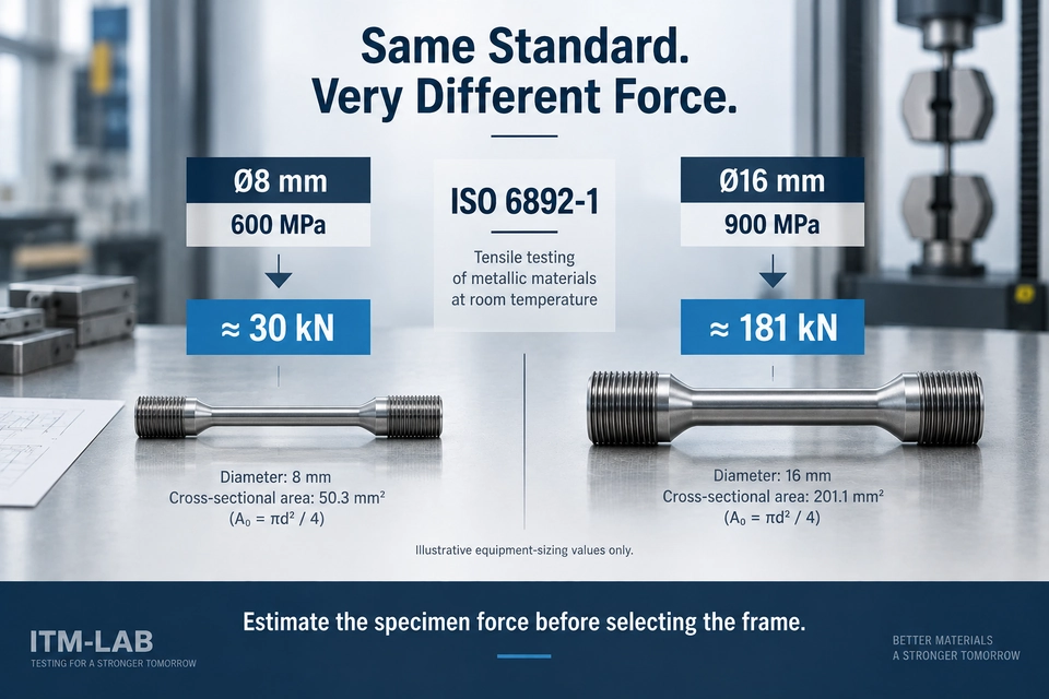
Take a machined round specimen with an 8 mm diameter.
Its cross-sectional area is:
A₀ = π × 8² / 4 ≈ 50.3 mm²
If the expected tensile strength is approximately 600 MPa:
50.3 mm² × 600 N/mm² ≈ 30,200 N
So we are looking at roughly:
30 kN
Now change only two things: specimen diameter and material strength.
Take a 16 mm diameter section and an expected tensile strength of 900 MPa.
The area becomes:
A₀ ≈ 201.1 mm²
and:
201.1 mm² × 900 N/mm² ≈ 181,000 N
or roughly:
181 kN
Same ISO standard.
About six times the force.
That difference is large enough to move the test into a completely different machine-capacity range.
It also shows why descriptions such as "steel tensile test" are not enough for equipment selection. Material grade matters, but geometry matters just as much.
For a flat specimen, the same first-pass logic applies:
A₀ = width × thickness
Then:
A₀ × expected tensile strength ≈ expected maximum force
The calculation should use a realistic upper expectation for the material and specimen being tested—not simply whichever nominal value is easiest to find on a datasheet.
These examples are illustrative equipment-sizing calculations only. They are not ISO 6892-1 prescribed specimen dimensions, tensile strengths, or acceptance values.
A 50 kN Frame Does Not Answer the Load-Cell Question
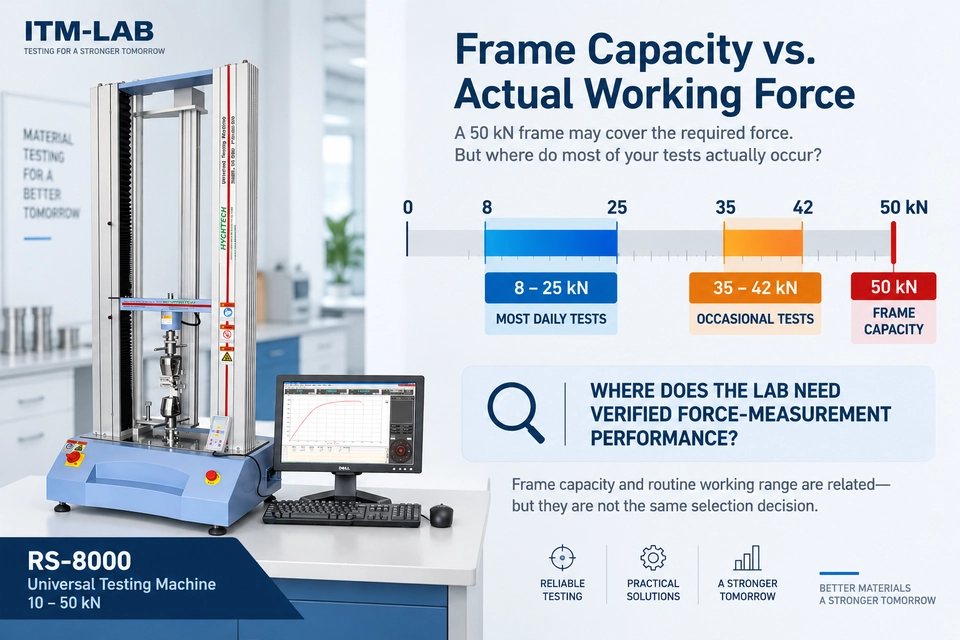
Suppose the largest specimen in a laboratory is expected to reach about 42 kN.
A 50 kN frame immediately looks relevant.
But now ask another question:
Where do most of the laboratory's tests actually occur?
Perhaps the workload looks like this:
Most daily specimens: 8–25 kN
Occasional specimens: 35–42 kN
That changes the equipment conversation.
The 42 kN figure is important when evaluating whether the frame has sufficient capacity.
It does not, by itself, describe the force range over which the laboratory routinely needs verified measurement performance.
These are related decisions, but they are not identical:
Expected upper force
→ helps define frame capacity.
Routine force distribution
→ helps define the force-measurement configuration.
Required verified measurement range
→ has to be considered when selecting and verifying the load-cell system.
ISO 7500-1 is the relevant ISO standard for calibration and verification of the force-measuring system of static uniaxial tension/compression testing machines; ISO currently lists the standard in its mechanical-testing catalogue.
This is one reason we do not like specifying a tensile system from maximum force alone.
Imagine two laboratories that both need a 50 kN frame.
One spends most of its time between 5 and 15 kN.
The other spends most of its time between 30 and 45 kN.
Mechanically, both may fit the frame.
From a measurement perspective, they are not the same workload.
Nor does buying a much larger frame automatically solve the problem. A higher capacity printed on the machine nameplate does not replace a properly selected and verified force-measurement configuration.
A better RFQ therefore gives us two numbers:
What is the highest force you reasonably expect?
and
Where do most of your specimens actually test?
Those two answers are more useful than "50 kN machine required."
The Customer Needs Rp0.2. Now What?
Until this point, we have mostly been talking about force.
Then the customer adds one line to the RFQ:
Required results: Rp0.2, Rm, A.
Now we need to talk about deformation measurement.
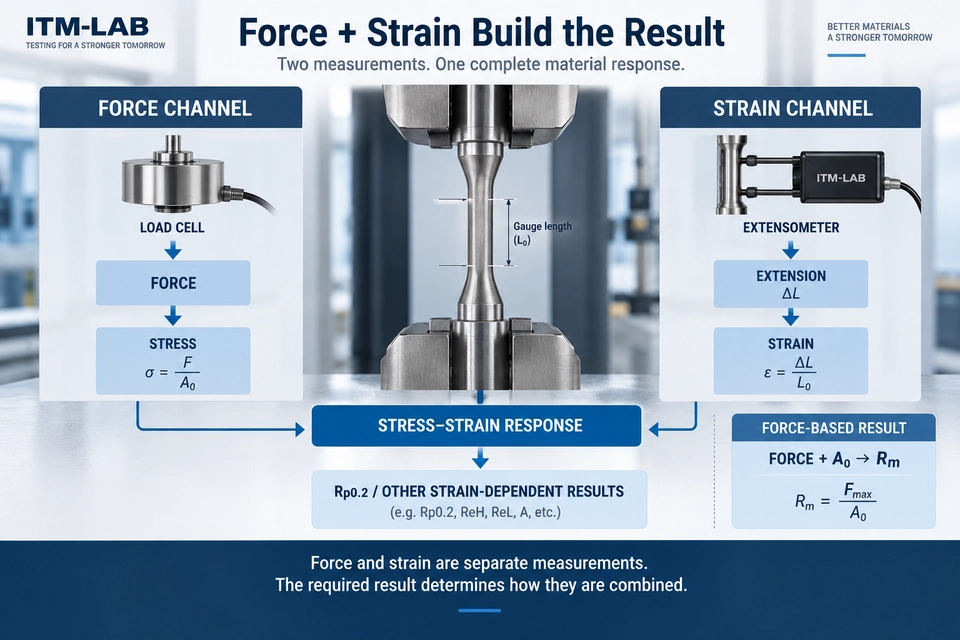
The load cell gives us force.
Combine that force with the original specimen cross-sectional area and we obtain stress.
But proof strength such as Rp0.2 depends on the relationship between stress and specimen strain.
That means we need another measurement channel.
Force channel
Load cell
↓
Force
↓
Stress
Strain channel
Extensometer
↓
Extension
↓
Strain
Bring those channels together and we can evaluate the relevant stress-strain response.
Public ISO 6892-1 testing guidance likewise identifies precise force measurement and specimen-extension measurement as key equipment requirements when determining the properties covered by the method.
This is why an extensometer should not be treated as a generic accessory added at the end of a quotation.
We need to know what it is expected to do.
What is the initial gauge length?
What strain range must it cover?
Which results are required?
Does it remain on the specimen into substantial plastic deformation, or is the test procedure configured differently?
And there is one more question:
Is the extensometer only measuring the specimen—or is its signal also controlling the machine?
That depends on the selected test-rate method.
Method A1 Changes the Control-System Requirement
This is where two machines that both claim to support ISO 6892-1 may need a closer comparison.
ISO 6892-1 distinguishes different approaches to test-rate control. For equipment selection, the useful distinction is:
Method A1
Closed-loop strain-rate control using the extensometer signal.
Method A2
Open-loop strain-rate control using a preselected or adjusted crosshead speed.
Method B
Control based on stress rate in the relevant region.
ZwickRoell's ISO 6892-1 technical guidance describes A1 as automatic closed-loop strain-rate control using extensometer feedback, while A2 uses a crosshead-speed approach to achieve the required strain rate.
That makes A1 particularly interesting from an equipment standpoint.
With A1, the extensometer is no longer just watching the specimen.
Its signal participates in the control loop.
Conceptually:
Specimen deformation
↓
Extensometer
↓
Measured strain rate
↓
Controller
↓
Drive / crosshead response
↓
Specimen deformation changes
and the loop continues.
So if the test program specifies Method A1, asking whether the software contains an "ISO 6892-1" method is not enough.
We would also want to know whether the controller can use extensometer feedback for the required closed-loop strain-rate control.
The extensometer, controller, drive system, grips, specimen stiffness and machine stiffness all become part of the behavior of the complete test system.
There is also a material-side complication that is easy to miss.
Metal does not always deform uniformly through yielding.
Some steels can show localized yielding behavior. When deformation localizes, an extensometer is measuring a defined gauge region while the specimen's deformation may not be distributed uniformly along the entire parallel length.
That makes the interaction between specimen behavior, extensometer position and control response more important than a simple software checkbox might suggest.
In other words:
"Method A1 capable" should describe the behavior of the measurement-and-control system—not merely the name of a test template.
For Method A2, the equipment conversation is different because the target strain-rate behavior is approached through crosshead speed rather than direct closed-loop extensometer feedback. ZwickRoell describes A2 as open-loop strain-rate control and notes that pre-testing/setup is required to account for the testing system and specimen stiffness.
Method B is different again.
There is no need to reproduce every ISO test-rate table here. The current standard and the applicable material/product specification should be used to establish the actual rates, tolerances and transitions.
For machine selection, the point is simpler:
Ask how the test is controlled—not only whether the standard number appears in the software.
Show Us the Specimen Before We Select the Grips
A machine can have enough force and still be unusable for the specimen sitting on your bench.
This is why the specimen drawing should reach the machine supplier before the gripping configuration is finalized.
Consider three common forms.
Flat specimens
We need more than the word "sheet."
Useful information includes:
width
thickness
grip-end dimensions
surface condition
expected force
A thin flat specimen and a thick plate-derived specimen do not necessarily create the same jaw requirement.
Round specimens
Now the contact geometry changes.
We need to know the grip-section diameter and the specimen-end design.
A plain cylindrical end, threaded end, shouldered specimen or another geometry may lead to a different load-introduction strategy.
Wire and small-diameter products
Wire creates its own problems.
The specimen must be held without uncontrolled slip, but excessive local contact stress can damage a small cross-section before the intended gauge section is properly evaluated.
Diameter, surface, material strength and expected force all matter.
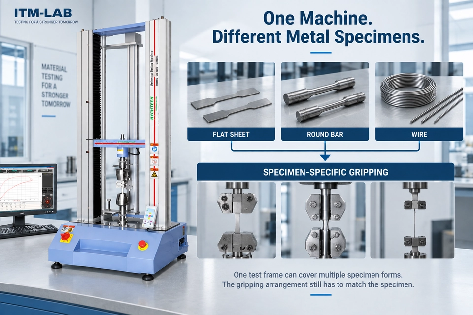
The machine frame may remain exactly the same while the specimen interface changes completely.
That is why:
One universal testing machine can cover multiple specimen families. One pair of jaws does not automatically cover them all.
If a laboratory plans to test sheet, round bars and wire on one frame, that should be part of the original equipment specification—not discovered after installation.
A 17.5 kN Specimen on a 50 kN Machine
Now put the decisions together.
A customer sends this RFQ:
| Requirement | Customer Information |
|---|---|
| Standard | ISO 6892-1 |
| Material | Stainless steel |
| Specimen | Flat |
| Width | 12.5 mm |
| Thickness | 2.0 mm |
| Expected Rm | 700 MPa |
| Required Results | Rp0.2, Rm, A |
| Volume | 100 specimens/day |
The first calculation is straightforward.
Original area:
12.5 × 2.0 = 25 mm²
Initial maximum-force estimate:
25 mm² × 700 N/mm² = 17,500 N
or:
≈ 17.5 kN
On paper, a 50 kN frame looks comfortable.
Then the rest of the RFQ starts to matter.
The customer needs Rp0.2.
Now we need a strain-measurement strategy.
Their internal procedure specifies Method A1.
Now the extensometer and controller have to work together as part of the strain-rate control system.
The specimen drawing shows several thicknesses.
Now we need to check whether the proposed jaw arrangement covers the complete specimen family.
Then we notice:
100 specimens/day.
Now loading, alignment, grip operation and extensometer handling become part of the laboratory workflow.
The 17.5 kN calculation was correct.
It simply was not the whole specification.
This distinction is important because machine quotations are often compared almost entirely by:
Maximum force
Price
Crosshead speed
Those specifications matter.
But they do not tell you whether the proposed system fits the actual test.
For this example, a useful configuration review would look more like:
17.5 kN expected specimen force
↓
Confirm upper force across all grades / specimen sizes
↓
Map routine working range
↓
Select force-measurement configuration
↓
Define flat-specimen grips
↓
Select extensometer
↓
Verify Method A1 control capability
↓
Review 100-test/day handling workflow
Only then do we have something close to a complete machine specification.
Turning the Test Requirement Into a Machine Configuration
For ITM-LAB, two relevant universal testing machine ranges for this type of work are:
RS-8000: 10–50 kN
RS-8000A: 100–300 kN
These are frame ranges, not automatic ISO 6892-1 selections.
The earlier examples make the distinction clear.
An Ø8 mm specimen at an illustrative 600 MPa gave us an estimated force around 30 kN.
That puts the application into a range where the RS-8000 can be evaluated—but it does not automatically complete the configuration.
Our Ø16 mm / 900 MPa example produced approximately 181 kN.
That moves the force requirement into the higher-capacity range where an RS-8000A configuration can be evaluated.
Again, the calculation is only the beginning.
After frame capacity, we still need:
Load cell
Grips
Extensometer
Control method
Travel / test space
Specimen range
Daily workflow
Steel does not automatically mean RS-8000A.
Aluminum does not automatically mean RS-8000.
The specimen decides the force.
The required results decide much of the measurement system.
The test method influences the control system.
Only after those pieces are defined does the machine model become meaningful.
What Should You Send With an ISO 6892-1 RFQ?
A long laboratory specification is not necessary.
A useful specimen drawing usually tells us more than several paragraphs of generic requirements.
For an initial configuration, send:
- material and grade;
- product form;
- specimen drawing;
- width and thickness, or diameter;
- expected tensile strength;
- expected upper test force, if already known;
- required results, such as Rp0.2, ReH/ReL, Rm and A;
- Method A1, A2 or B if your procedure specifies it;
- gauge length / extensometer requirement;
- smallest and largest specimen families;
- approximate tests per day.
If you do not know the expected force, send the material specification and specimen drawing.
That gives us enough information to start the calculation rather than guessing from the standard number.
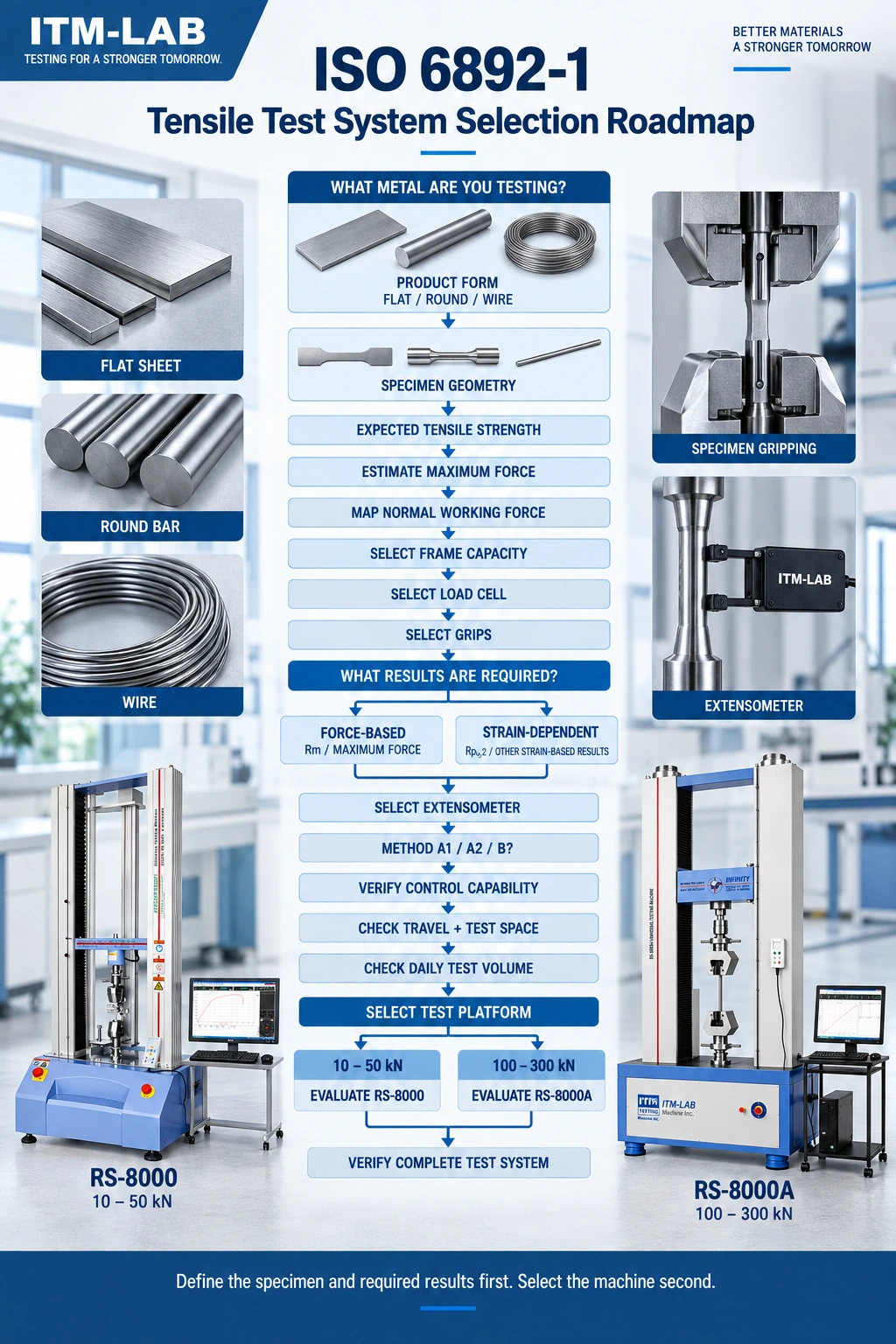
ISO 6892-1 Tensile Test System Selection Roadmap
ISO 6892-1 Tensile Testing Machine FAQ
What machine capacity do I need for ISO 6892-1?
There is no single machine capacity associated with ISO 6892-1.
For initial sizing, estimate the expected upper specimen force from the original cross-sectional area and expected tensile strength:
Expected Force ≈ A₀ × Expected Tensile Strength
Then consider the normal working-force range, load-cell configuration, grips, extensometer, required control method and specimen family before finalizing the machine.
Do I need an extensometer for ISO 6892-1?
It depends on the properties and control method required by the test program.
Where specimen strain must be measured to determine strain-dependent properties, an appropriate extensometer becomes part of the measurement system. For Method A1, the extensometer signal is also used for closed-loop strain-rate control.
The correct extensometer therefore depends on factors such as gauge length, measurement range, required result and control strategy.
What is the difference between ISO 6892-1 Method A1, A2 and B?
From an equipment-selection perspective, Method A1 uses closed-loop strain-rate control with extensometer feedback. Method A2 is an open-loop strain-rate approach using crosshead speed, while Method B controls the test based on stress rate in the relevant region.
The current standard should be used for the actual rates, tolerances and stage transitions.
How do I estimate tensile force before selecting a machine?
For a first-pass equipment estimate:
Expected Maximum Force ≈ Original Cross-Sectional Area × Expected Tensile Strength
For a round specimen:
A₀ = πd² / 4
For a rectangular specimen:
A₀ = width × thickness
Use an appropriate upper expectation for the material and specimen range being tested. The result is an equipment-sizing estimate, not a substitute for the ISO test procedure.
Can one tensile testing machine test flat, round and wire specimens?
Potentially, yes—provided the frame, force-measurement system, travel and other machine requirements cover the complete test program.
The gripping arrangement may still change between specimen families. Flat specimens, round specimens and wire present different contact geometries and different risks of slip or local damage.
Are ISO 6892-1 and ASTM E8/E8M interchangeable?
No. Both address tensile testing of metallic materials, but they are separate standards and should not be treated as interchangeable procedures.
If a project specifies ASTM E8/E8M, configure and run the test according to the applicable ASTM requirements. If it specifies ISO 6892-1, use the ISO method.
For laboratories working with both systems, this is another reason to define the required standards before configuring software, extensometry and test procedures.
The Standard Defines the Test. The Specimen Defines the System.
An inquiry for an ISO 6892-1 tensile testing machine sounds specific.
For an equipment engineer, it is the start of the conversation.
We still need to see the specimen.
From there, the selection path becomes much clearer:
Specimen Geometry
↓
Expected Force
↓
Routine Working Range
↓
Load Cell
↓
Grips
↓
Required Results
↓
Extensometer
↓
Control Method
↓
Machine
That sequence prevents a common mistake: selecting a universal testing machine from maximum capacity first and trying to make the actual test fit it afterward.
If you are planning an ISO 6892-1 system, send us the specimen drawing, material grade, expected tensile strength, required results, test-rate method and daily test volume.
Those details are far more useful for configuring the test system than the standard number alone.
