
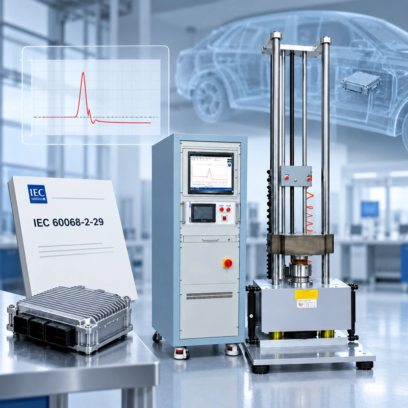
If a drawing still calls for IEC 60068-2-29, do not assume you simply need an “IEC 60068-2-29 bump tester.”
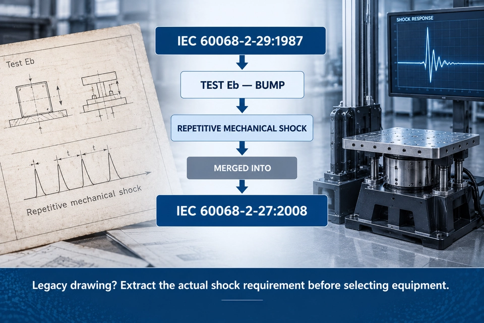
IEC 60068-2-29:1987 is a legacy standard. Its Test Eb: Bump content was merged into IEC 60068-2-27:2008, which covers specified severities of non-repetitive and repetitive mechanical shocks.
That changes how an equipment inquiry should be handled.
The real question is not:
“Which machine complies with IEC 60068-2-29?”
It is:
“What mechanical pulse, repetition history and loaded configuration does the legacy requirement actually call for?”
A practical selection path is:
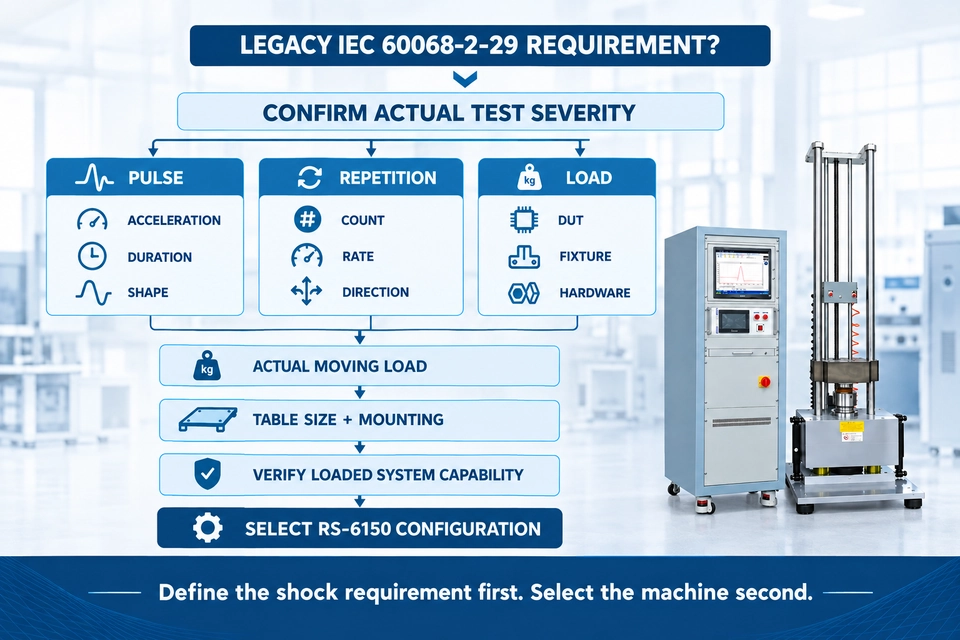
Legacy Requirement → Pulse → Repetition → DUT → Fixture → Actual Moving Load → Loaded System Capability → Equipment
For ITM-LAB, the relevant equipment platform to evaluate is the RS-6150 Series Vertical Impact Crash Tester.
IEC 60068-2-29 Is a Legacy Standard—Here Is What That Means
IEC 60068-2-29:1987 defined Test Eb: Bump, a repetitive mechanical shock test intended to determine whether a specimen could withstand specified severities of bump.
The standard was later replaced, and its bump-test content was incorporated into IEC 60068-2-27:2008.
IEC 60068-2-27:2008 is therefore the current IEC reference that incorporates the former IEC 60068-2-29 bump-test content.
That creates two different situations in practice.
New Test Program
If a new qualification program is being developed, the applicable current shock requirement should be established from IEC 60068-2-27 and the relevant product specification.
Legacy Drawing or Customer Specification
If an existing drawing explicitly references IEC 60068-2-29, do not casually replace the standard number.
First identify the actual test requirement:
- acceleration;
- pulse duration;
- pulse shape;
- number of bumps;
- repetition rate;
- test direction;
- DUT condition;
- fixture;
- acceptance criteria.
Only then should the test system be selected.
| Item | IEC 60068-2-29 |
|---|---|
| Edition | IEC 60068-2-29:1987 |
| Test | Test Eb |
| Test Name | Bump |
| Mechanical Input | Repeated discrete shock pulses |
| Main Purpose | Ability to withstand specified severities of bump |
| Current Status | Replaced |
| Current IEC Reference | IEC 60068-2-27:2008 |
| Equipment Direction | Controlled mechanical shock system |
A legacy standard number is the starting point.
The mechanical requirement behind it determines the test.
A Bump Is Not Just a “Small Shock”
The word bump can sound mild.
Mechanically, that is misleading.
A bump test uses short-duration shock events applied repeatedly to a mounted DUT. Its engineering value comes from that repetition.
One pulse may reveal a weak bracket.
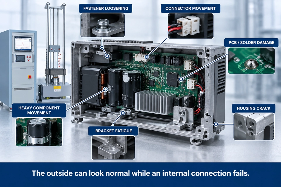
Thousands of repeated pulses may reveal a fastener slowly loosening, an intermittent connector, a solder joint beginning to crack or an internal component shifting in its mount.
The question changes from:
Can the product survive this event?
to:
Can the product continue to meet its requirement after repeated mechanical shocks?
The DUT remains mounted to a fixture or machine table during the test.
That puts bump testing in the controlled mechanical shock family—not in the same category as free-fall drop testing.
One Shock vs Repeated Mechanical Events
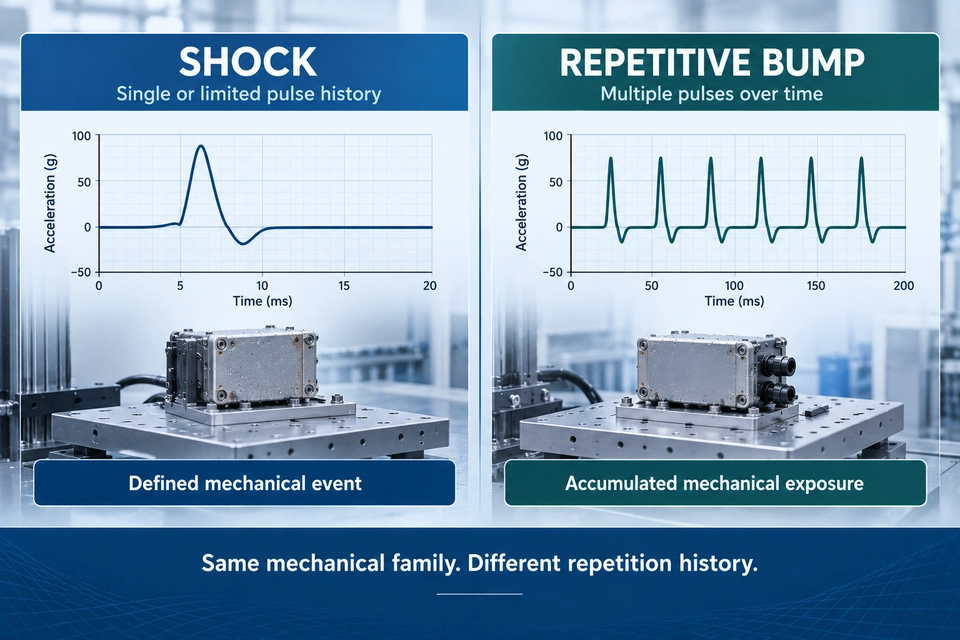
A single shock and a repeated bump sequence may use similar pulse shapes.
They do not create the same mechanical history.
Single or Limited Shock
The engineer may be looking for:
- structural survival;
- mounting integrity;
- component retention;
- instantaneous electrical interruption;
- permanent deformation.
Repeated Mechanical Shock
Repetition can expose cumulative effects such as:
- fastener loosening;
- interface wear;
- progressive cracking;
- repeated relative movement;
- intermittent electrical faults;
- functional drift.
A repetitive test therefore cannot be judged from the first successful pulse.
The complete event history matters.
Six Parameters That Define the Test
A mechanical bump or repetitive shock test cannot be defined by one number.
A statement such as:
“We need 50 g.”
is incomplete.
The test is a combination of parameters.
| Parameter | Why It Matters |
|---|---|
| Acceleration | Defines peak mechanical input |
| Pulse Duration | Influences DUT response and load transfer |
| Pulse Shape | Defines the acceleration-time history |
| Number of Bumps | Defines total repeated exposure |
| Repetition Rate | Defines how quickly events are applied |
| Direction | Defines the load path through the DUT |
Three deserve particular attention during equipment selection.
Pulse Duration Changes the Test
Consider:
50 g / 6 ms
and
50 g / 11 ms
The peak acceleration is identical.
The mechanical input is not.
Pulse duration affects how the shock interacts with:
- the DUT structure;
- mounting points;
- heavy internal components;
- fixture;
- dynamic response of the assembly.
This is why a machine cannot be selected from acceleration alone.
Repetition Rate Is Not a Minor Detail
This becomes especially important when a legacy Test Eb requirement specifies a large number of bumps.
A machine may produce one correct pulse without necessarily being suitable for the complete repetitive sequence.
The equipment should also be checked against:
- required event count;
- repetition rate;
- pulse stability;
- total test duration;
- machine recovery behavior.
Engineering Note: A compliant single pulse does not automatically prove capability for a legacy high-count bump schedule.
Direction Changes the Load Path
Mechanical response is directional.
A housing that is strong vertically may behave differently laterally. A connector may be stable in one axis and vulnerable in another.
The test plan should therefore define the required axis, direction and mounting orientation.
Repetitive Shock Does Not Automatically Mean “Legacy Bump”
This distinction matters for current projects.
A repetitive shock test may now be specified directly under IEC 60068-2-27.
That does not make it an IEC 60068-2-29 test.
The old bump terminology may still appear in:
- historical product drawings;
- older customer specifications;
- legacy qualification documents;
- inherited internal procedures.
The actual requirement should always be read from the applicable document.
In other words:
Repeated shock ≠ automatically IEC 60068-2-29
and
IEC 60068-2-29 reference ≠ automatic equipment compliance
The specified test conditions decide.
Where Repeated Shock Finds Weakness
Repeated mechanical shock can reveal failures at several levels.
Mechanical
Fasteners, brackets, housings and internal retention systems may loosen, crack, deform or shift.
Electrical
Connectors, terminals, wiring, PCBs and solder joints can degrade under repeated inertial loading.
Functional
A product may remain physically intact while developing:
- intermittent operation;
- calibration drift;
- communication errors;
- signal interruption;
- control instability.
A DUT can look intact after the test and still fail electrically.
That is why PASS/FAIL criteria should be defined before testing starts.
Bump vs Shock vs Vibration vs Drop: Do Not Select the Wrong Machine
All four tests apply mechanical stress.
The load mechanism is different.
| Test | Mechanical Input | DUT Condition | Main Question | Equipment |
|---|---|---|---|---|
| Bump / Repetitive Shock | Repeated discrete pulses | Mounted | Can the DUT withstand repeated shocks? | Mechanical shock machine |
| Shock | Defined short-duration pulse | Mounted | Can the DUT survive the specified shock? | Mechanical shock machine |
| Vibration | Continuous sinusoidal or random excitation | Mounted | Can the DUT withstand sustained vibration? | Vibration shaker |
| Drop | Free-fall impact | Released | Can the DUT survive impact after falling? | Drop tester |
A simple distinction is:
Shock: defined pulse.
Bump: repeated discrete pulse history.
Vibration: continuous excitation.
Drop: free-fall impact.
If the DUT is bolted to a fixture or table, you are already dealing with a very different boundary condition from free fall.
For ITM-LAB equipment:
Mechanical Shock / Repetitive Pulse → RS-6150
Random / Sinusoidal Vibration → RS-V Series
Free-Fall Drop → RS-DP / RS-315 / RS-320 Series
Where Is Repetitive Mechanical Shock Testing Used?
The underlying test concept is relevant wherever mounted equipment may experience repeated short-duration mechanical events.
| Industry | Typical DUT | Possible Weakness |
|---|---|---|
| Automotive Electronics | ECU, sensors, connectors | Mounting, connector and PCB failures |
| Industrial Electronics | Controllers, instruments | Fastener loosening, internal retention |
| Telecom | Communication modules | Mounting and connector durability |
| Aerospace / Avionics | Mounted electronic assemblies | Structural and connection integrity |
| Electrical Equipment | Relays, switches, assemblies | Mechanical and electrical degradation |
| Rugged Electronics | Industrial portable equipment | Housing and internal mounting weakness |
The industry does not determine the test standard.
The product requirement does.
How to Handle a Legacy IEC 60068-2-29 Drawing
Suppose a customer sends:
“Please quote a bump test machine according to IEC 60068-2-29.”
Do not start with machine size.
Start with the requirement.
1. Confirm the Document Revision
Check the drawing revision, customer specification, date and referenced IEC edition.
This establishes whether the legacy reference is intentional.
2. Extract the Pulse
Identify:
Acceleration + Pulse Duration + Pulse Shape
These define the mechanical event much more clearly than the word bump.
3. Extract the Repetition Requirement
Confirm:
Number of Bumps + Repetition Rate + Direction
These define the repeated exposure.
4. Define the DUT
Record:
Dimensions + Mass + Mounting Points + Operating Condition + Monitoring Requirement
5. Define the Fixture
Confirm:
Dimensions + Mass + Stiffness + Interface + Mounting Orientation
6. Calculate the Actual Moving Load
Use:
DUT + Fixture + Mounting Hardware
not DUT mass alone.
Only after these values are known should the machine configuration be evaluated.
The Fixture Is Part of the Test
Fixture design is not an accessory decision made after machine selection.
It affects how the shock pulse reaches the DUT.
An inadequate fixture may introduce:
- unwanted flexibility;
- resonance;
- local bending;
- loose mounting;
- inconsistent pulse transfer.
That creates an important question:
Are you measuring the DUT response—or the fixture response?
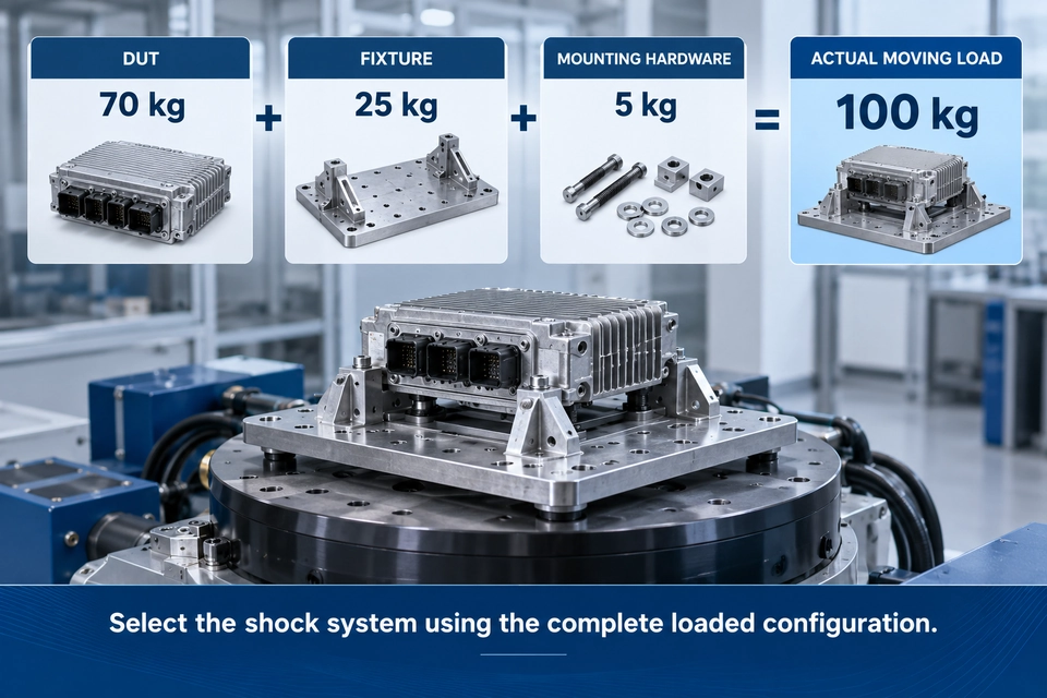
Fixture mass also changes equipment selection.
Consider:
DUT: 70 kg
Fixture: 25 kg
Mounting Hardware: 5 kg
The actual moving load is:
100 kg
not 70 kg.
For heavier DUTs, the fixture can move a project into a completely different machine configuration.
Maximum g Is a Catalogue Number. Loaded Pulse Capability Is the Real Question.
This is one of the easiest mistakes to make when comparing shock machines.
A customer sees:
Maximum Acceleration: 600 g
and concludes:
“Our requirement is only 50 g, so this machine is more than enough.”
Not necessarily.
A 600 g machine rating does not mean 600 g is available at every payload, pulse duration or table configuration.
Nor does it mean every lower acceleration can automatically be generated under every loaded condition.
The actual question is whether the complete loaded system can reproduce the required pulse.
That means checking:
Payload + Pulse Shape + Acceleration + Pulse Duration + Fixture + Table Size
The required pulse should always be verified at the actual loaded condition.
That is much more meaningful than comparing a single maximum-g catalogue number.
Where RS-6150 Fits
For ITM-LAB, the relevant platform to evaluate is the:
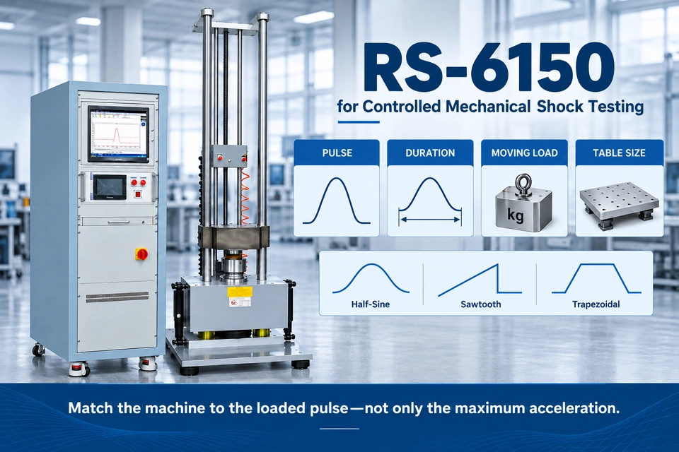
RS-6150 Series Vertical Impact Crash Tester
The RS-6150 is designed for controlled mechanical shock pulse testing.
Available system configurations support:
- half-sine;
- sawtooth;
- trapezoidal pulse shapes;
- different payload classes;
- multiple table sizes.
For legacy IEC 60068-2-29 inquiries, RS-6150 is the appropriate ITM-LAB mechanical shock product family to evaluate.
However, the correct statement is not:
“Every IEC 60068-2-29 requirement is automatically supported.”
A more accurate engineering position is:
RS-6150 is the relevant ITM-LAB mechanical shock platform for legacy IEC 60068-2-29 bump requirements. Final capability should be verified against the required pulse, repetition conditions, actual moving load and fixture.
RS-6150 Configuration Range
| Configuration | Test Table | Maximum Load | Max. Half-Sine Acceleration |
|---|---|---|---|
| A | 400 × 400 mm | 30 kg | 1000 g |
| B | 700 × 800 mm | 100 kg | 600 g |
| C | 1200 × 1200 mm | 300 kg | 300 g |
| D | 1500 × 1500 mm | 1000 kg | 150 g |
Available half-sine pulse-duration ranges depend on the configuration:
A: 1–30 ms
B: 3–30 ms
C: 5–30 ms
D: 8–30 ms
The relationship is important.
Smaller configurations can reach higher acceleration.
Larger configurations support heavier moving loads and larger DUTs.
The selection is therefore a balance between:
Acceleration + Pulse Duration + Moving Load + Table Size
not a race for the highest g rating.
A Practical Selection Example
A customer provides:
DUT: Industrial electronic controller
Dimensions: 650 × 520 × 380 mm
DUT Mass: 80 kg
Looking only at the product weight suggests an 80 kg requirement.
But suppose the mounting fixture weighs:
25 kg
and the mounting hardware adds:
5 kg.
The actual moving load becomes:
110 kg
Now add the test requirement:
Pulse Shape: Half-sine
Acceleration: 50 g
Pulse Duration: 11 ms
Repetition: Defined by legacy qualification specification
The real equipment question is now:
Can the selected RS-6150 configuration reproduce a 50 g / 11 ms half-sine pulse at approximately 110 kg actual moving load, with the required repetition sequence?
That is a useful selection question.
“80 kg product, 50 g test” is not enough.
Bump / Mechanical Shock Test Equipment Selection Roadmap
Common Selection Errors
Several mistakes appear repeatedly when evaluating bump and mechanical shock equipment.
Treating IEC 60068-2-29 as a current standard — it is a legacy reference whose bump-test content was incorporated into IEC 60068-2-27.
Comparing maximum g only — acceleration is only one part of the pulse.
Ignoring repetition conditions — one correct pulse does not prove high-count repetitive capability.
Using DUT mass as the machine load — fixture and mounting hardware also move.
Treating bump as vibration — discrete shock pulses and continuous vibration are different mechanical inputs.
Treating bump as drop testing — mounted shock and free-fall impact have different boundary conditions.
IEC 60068-2-29 Bump Test FAQ
Is IEC 60068-2-29 still current?
No. IEC 60068-2-29:1987 is a legacy standard. Its Test Eb bump-test content was incorporated into IEC 60068-2-27:2008.
What replaced IEC 60068-2-29?
IEC 60068-2-27:2008 is the current IEC reference that incorporates the former IEC 60068-2-29 bump-test content and addresses specified non-repetitive and repetitive shocks.
What is the difference between bump and shock testing?
The traditional bump concept emphasizes repeated discrete shock events. Shock testing may involve non-repetitive or repetitive pulses depending on the applicable requirement.
Is bump testing the same as vibration testing?
No. Bump testing uses discrete mechanical shock events. Vibration testing applies continuous sinusoidal or random excitation.
Which ITM-LAB machine is used for bump / repetitive shock testing?
The relevant ITM-LAB platform is the RS-6150 Series Vertical Impact Crash Tester. Final suitability should be verified against the required acceleration, pulse duration, waveform, repetition conditions, actual moving load and fixture.
Configure Your Mechanical Shock Test System
When requesting equipment, do not send only:
“IEC 60068-2-29, 80 kg product.”
Send the actual mechanical requirement.
Pulse
Acceleration · Pulse Duration · Pulse Shape
Repetition
Number of Bumps / Shocks · Repetition Rate · Test Direction
Load
DUT Dimensions · DUT Mass · Fixture Mass · Mounting Hardware
Monitoring
Operating State · Electrical Continuity · Functional Check
With this information, ITM-LAB can evaluate the appropriate RS-6150 configuration against the actual loaded mechanical shock requirement.
Define the shock requirement first. Select the machine second.
Send Your Shock Test Requirement
View RS-6150 Mechanical Shock Test System
