
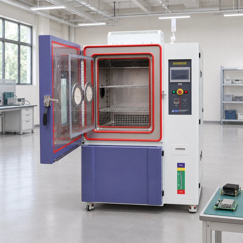
Before installing an environmental test chamber, confirm the move-in route, floor suitability, operating and service space, electrical supply, room heat rejection, water connections and drainage. The site should be ready before delivery, with startup and handover responsibilities agreed. This guide uses an ITM-LAB 408 L chamber manual to show how those requirements translate into a practical installation plan.
A chamber can fit through the laboratory door and still create an installation problem. Its door may open into the aisle, its drain may be difficult to connect, or an adjacent machine may block the panel a service engineer needs to remove. Review the complete layout while the equipment is being specified.
What to Confirm Before the Chamber Arrives
Use the following checklist with your facilities team and chamber supplier. Record the document or drawing revision used for each decision.
| Item to confirm | Information to obtain from the supplier | Site preparation |
|---|---|---|
| Delivery and positioning | Packed and unpacked dimensions, shipping weight, lifting instructions | Check the unloading area, doors, turns, elevator and final move-in route. |
| Floor and room | Operating weight, support arrangement and specified ambient conditions | Confirm floor suitability, levelness, vibration exposure and ventilation. |
| Working and service space | Clearance drawing, door swing and removable-panel access | Reserve room for loading, connections and maintenance. |
| Electrical supply | Voltage, phase, frequency, rated current and connection details | Have a qualified electrician review the supply and protective measures. |
| Cooling arrangement | Condenser type, heat-rejection data and any cooling-water requirements | Confirm room cooling capacity or the external cooling system. |
| Water and drainage | Applicable water systems, connection locations and supply specifications | Prepare the required water source and accessible drain route. |
| Powered specimens | Specimen power needs, cable entry and optional switching interfaces | Provide a suitable specimen supply and agree cable routing. |
| Commissioning | Installation tasks, startup checks, training and records | Assign responsibilities and arrange access for the agreed work. |
Scope of the examples: Dimensions and numeric installation guidance below refer to the supplied ITM-LAB GDW-408L manual. The nameplate, approved drawings and installation documents issued for your equipment govern the final site requirements.
Measure the Move-In Route Before Delivery
The manual asks buyers to consider small doorways and goods elevators when confirming the chamber’s outside dimensions at the ordering stage. Start at the unloading point and follow the full route to the installation position.
The GDW-408L dimensional table lists a nominal external size of 850 mm wide × 1750 mm high × 1600 mm deep. Check the delivery route using the approved outline and packing drawings, including projecting parts and the space needed for handling.
For example, a doorway slightly wider than an 850 mm cabinet does not establish that the delivery route is suitable. The packed unit may be wider, and a turn immediately beyond the doorway may restrict movement. Record the narrowest opening, lowest overhead obstruction and tightest turn along the route. Obtain the shipping and operating weights separately so the handling team and facilities team can assess their respective loads.
The manual instructs handlers to support the base at its structural members and prevent the chamber from overturning. Agree unloading, lifting, pallet removal and positioning arrangements with the supplier and handling team before the truck arrives. On receipt, check the equipment and accessories against the packing list and record any damage.
If installation is delayed, follow the manual’s storage instructions. Keep the chamber level and protected from dust, rain and corrosive materials.
Reserve Space for Door Opening, Airflow and Maintenance
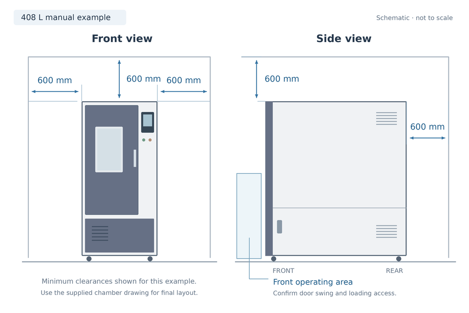
For this 408 L example, Section 2.6 specifies at least 600 mm between the chamber and walls or other machines. Its accompanying drawing shows clearance at the sides, rear and above the cabinet.
Use that clearance together with the door swing, specimen-loading space and service-panel access shown on the approved layout. Check how the room will work with the door fully open, a loading cart in position and someone standing at the controller. Walk-in chambers and systems with separate conditioning units require their own project layouts.
The manual warns that inadequate space can affect cooling and humidity performance. Reserving service access also allows routine cleaning and inspection without having to move equipment each time.
Choose an Indoor Location With Suitable Room Conditions
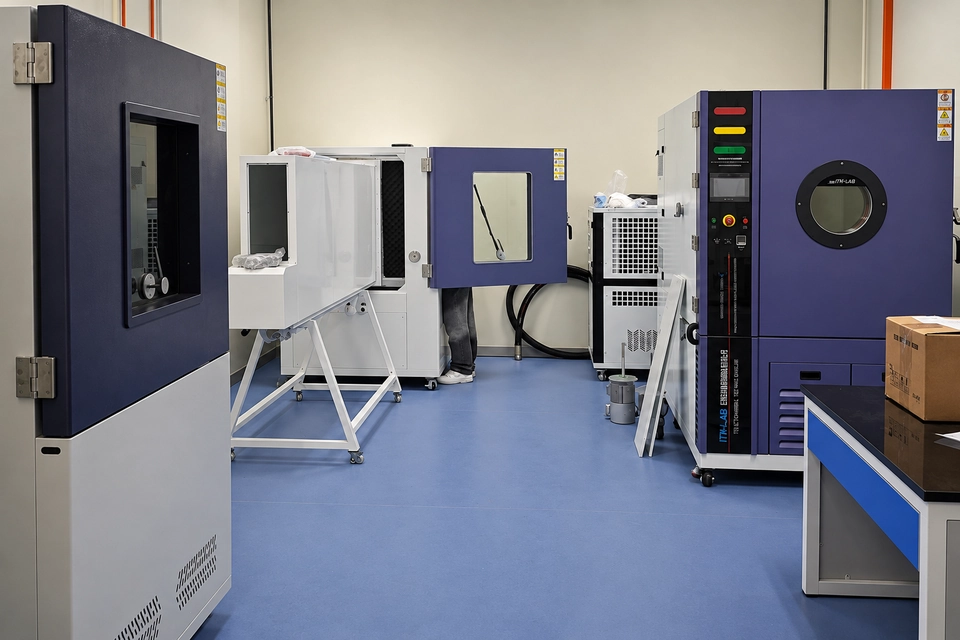
The installation section calls for a flat, vibration-free indoor location, checked with a spirit level. It also calls for good ventilation, limited dust and moisture, protection from direct sunlight, and separation from heat sources and flammable or explosive materials.
Room temperature deserves attention during planning. The manual warns that poor ventilation or a room temperature above 35°C can slow cooling or prevent the chamber from reaching the required low temperature. Do not treat 35°C as a guaranteed operating limit or a promise of rated performance below it. Obtain the specified ambient range and the conditions behind the quoted performance.
Give the facilities team the supplier’s heat-rejection data, the condenser arrangement and the expected operating schedule. Include other equipment that will run at the same time. For an air-cooled installation, check where the condenser draws in air and discharges it, and keep that path clear.
Specimen heat load describes heat released inside the test space; it does not replace the chamber heat-rejection data needed for room HVAC planning. For a fuller comparison of condenser arrangements, see air-cooled and water-cooled environmental test chambers.
Confirm the Electrical Supply for the Supplied Chamber
Electrical connections must be completed by qualified personnel. Section 2.7 directs users to the nameplate for voltage and frequency and requires the chamber to be earthed.
Before delivery, send the site supply details to the supplier and ask your electrician to review the chamber’s electrical documents. Confirm voltage, phase, frequency, rated current, the required connection arrangement and protective measures.
The manual warns that voltage variation beyond ±10% can cause faults or unstable operation. The electrician should assess the actual supply against the equipment specification.
Use the specified protective-earth connection and verify the neutral and phase requirements from the electrical drawing. The electrician should determine cable sizing, protective devices and the final connection from the equipment documents and applicable local requirements. Chamber volume alone is not a reliable basis for selecting a 220 V or 380 V supply.
Provide a Suitable Supply for Powered Specimens
The manual states that specimens requiring power need a separate, suitable supply because the chamber’s own power provision is sized for the equipment. It also describes optional specimen switching control.
For powered electronic assemblies, agree the specimen supply, cable route through the test port and any required switching interface before installation. Confirm whether an interface supplies power or provides a control signal, together with its rating.
Include specimen heat dissipation in the application review. See how to calculate DUT heat load.
Identify Which Water Connections the Configuration Needs
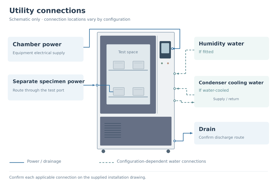
Review condenser cooling water, humidity supply water and drainage as separate items on the installation schedule. Ask the supplier to identify each applicable connection, its location and the conditions it must meet.
| System | Confirm before preparing the site |
|---|---|
| Condenser cooling water, where fitted | Required inlet conditions, flow, pressure, water quality, return connection and heat-rejection duty. |
| Humidity supply, where fitted | Approved water quality, filling or supply arrangement, and access for inspection and maintenance. |
| Chamber drainage | Connection size, discharge location and routing requirements for the supplied unit. |
Select the water infrastructure from the condenser configuration and its specified duty, rather than chamber volume alone. A water-cooled configuration may connect to an appropriate facility water system, cooling tower arrangement or chiller.
Review the selected equipment’s required water conditions and the complete installation with the supplier. Outdoor plant needs a suitable location and access. An indoor chiller also needs its own space, utilities and heat-rejection arrangement.
The manual directs users to connect the rear drain after the chamber is positioned and recommends keeping supply and drainage runs as short as practical. Plan that connection while access to the rear is still available.
For configurations using humidity control, the manual adds checks for adequate water supply and the wet-bulb cloth. These checks belong in the startup procedure for the applicable humidity system.
Agree Who Prepares, Connects and Checks Each Item
An installation requirement is only useful when someone is responsible for completing it. Use the following working sheet during the pre-delivery review. Suggested participants identify who should be involved; the project agreement determines the actual scope.
Project / chamber: __________
Layout revision: __________
Review date: __________
| Preparation or check | Suggested participants | Assigned owner | Status / evidence | Due date |
|---|---|---|---|---|
| Unloading and complete move-in route | Customer, supplier, handling contractor | ______ | ______ | ______ |
| Floor suitability and final position | Facilities team, supplier | ______ | ______ | ______ |
| Door swing, loading area and service access | Laboratory team, supplier | ______ | ______ | ______ |
| Electrical supply and protective measures | Qualified electrician, supplier | ______ | ______ | ______ |
| Room cooling or condenser-water system | Facilities team, cooling contractor, supplier | ______ | ______ | ______ |
| Applicable humidity water and drainage | Facilities team, supplier | ______ | ______ | ______ |
| Powered-specimen connections | Test engineer, qualified electrician, supplier | ______ | ______ | ______ |
| Startup, training and acceptance records | Customer representative, supplier | ______ | ______ | ______ |
Record each item as ready, pending or not applicable. Link the supporting drawing, photograph or contractor confirmation. Give every open item an owner and completion date before scheduling the affected installation work.
Additional Planning for Walk-In Chambers
Walk-in projects need an agreed assembly and connection sequence. Confirm how panels, doors and conditioning equipment will reach the room, where assembly can take place, and which building works must be ready before the installation team arrives.
Extend the responsibility sheet to cover panel assembly, floor preparation, pipework and controls connections. Mark who supplies each item, who installs it and who confirms completion.
Use the walk-in project drawings for clearances, structural loads and utility values; the 600 mm cabinet example above is not a walk-in layout specification.
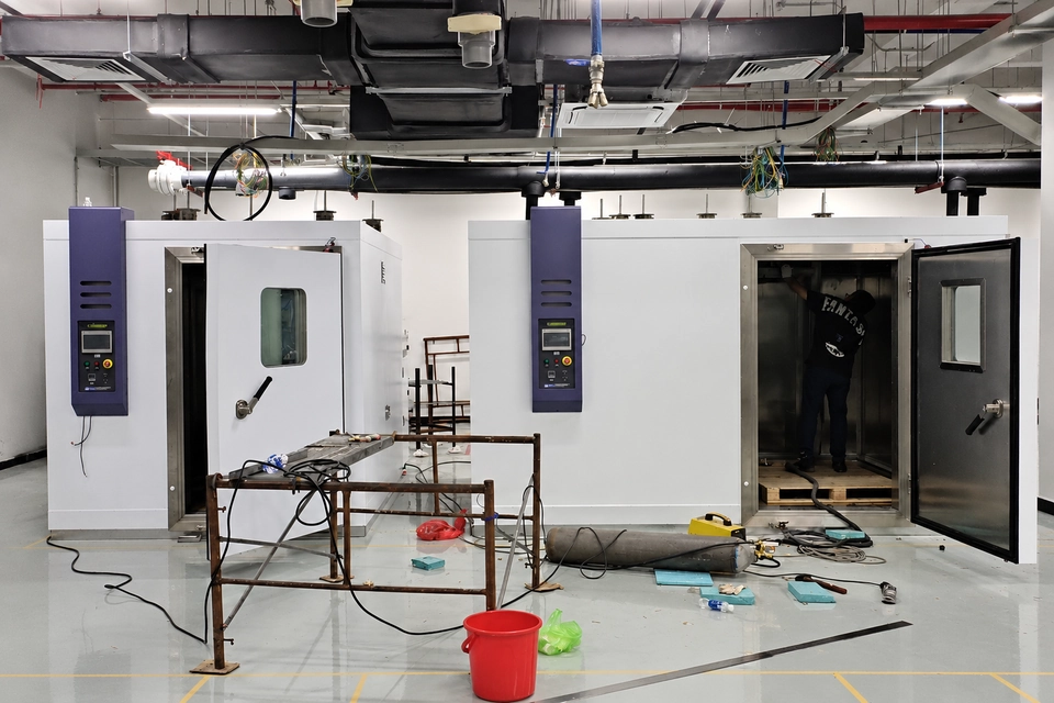
A site walk-through before delivery helps resolve access and connection details while the building team can still act on them. Keep the agreed plan available to both the installation team and the customer representative.
Complete Startup and Handover Before Routine Testing
Section 2.8 calls for checking the electrical and drain connections, removing protective packaging from the specimen racks and sealing the test port for low-temperature operation. It also emphasizes operator training.
Use the following as a handover checklist alongside the supplied startup procedure.
| Check | Record at handover |
|---|---|
| Positioning | Chamber level checked and the agreed clearance and operating areas available. |
| Connections | Electrical work verified by qualified personnel, drain connected and applicable water systems ready. |
| Interior and test ports | Packaging removed, racks inspected and test-port seals checked. |
| Specimen interfaces | Separate specimen supply and any switching controls identified. |
| Initial operation | Agreed functional checks completed and any open items recorded. |
| Operator handover | Staff trained on startup, shutdown, alarms and routine checks, with manuals available. |
Startup checks establish that the installation is ready for operation. A site acceptance test, when included in the purchase scope, verifies the agreed performance under defined conditions. Specify its test profile, load condition, measurement method, limits and report in advance.
Agree who corrects any failed item and how the repeat check will be recorded. For the commercial scope of factory and site checks, see how to compare environmental test chamber quotations.
Keep Maintenance Access Available After Installation
The maintenance section calls for regular condenser cleaning, with monthly cleaning listed in its schedule. Place the chamber so the specified cleaning area remains accessible after benches, racks and other machines are installed.
The manual assigns adjustment, maintenance and repair to qualified technicians. At handover, identify the access needed for the condenser, electrical compartment, drain and any water system. Include those locations in the room’s maintenance plan.
Review Your Installation Site With ITM-LAB
Preparing a new laboratory or replacing an existing chamber? Send ITM-LAB a marked room layout and site photographs, the narrowest move-in route dimensions, available power, and water and drainage details. Add the intended test profile, specimen dimensions, operating state and estimated heat dissipation for powered products.
These inputs allow the chamber configuration and installation requirements to be reviewed together. Explore the ITM-LAB environmental test chamber range, or contact ITM-LAB to discuss your installation site.
Frequently Asked Questions
How much clearance does an environmental test chamber need?
The supplied ITM-LAB GDW-408L manual specifies at least 600 mm between the chamber and walls or other machines, with side, rear and overhead spacing shown in its drawing. Confirm the door swing, loading space and service access for the actual configuration before approving the layout.
Can powered specimens use the chamber’s electrical supply?
The manual requires a separate, suitable supply for powered specimens. Agree the specimen connection and any optional switching interface with the supplier. Have qualified personnel verify the installation against the chamber and specimen electrical requirements.
Does every environmental chamber need cooling water?
The required connections depend on the supplied cooling configuration. Ask the supplier to list condenser cooling water, humidity water and drainage separately, including the specifications for each applicable connection.
What should be ready before the installation engineer arrives?
Complete the agreed delivery route, floor preparation and utility work. Have the approved layout, electrical documents and connection schedule available, assign a customer representative, and arrange the operators who will attend training.
Technical Reference
ITM-LAB GDW-408L operating manual: Sections 2.3–2.8, covering handling, installation location, utility connections and pre-operation checks; Section 4, covering maintenance.
The responsibility sheet and site-planning examples in this article are practical planning aids. Equipment-specific requirements remain defined by the supplied technical documents.
