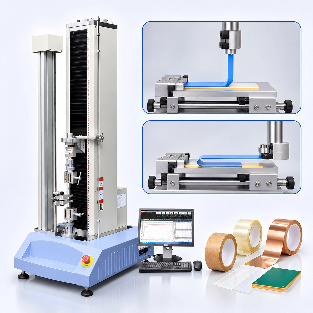
A 90° peel test and a 180° peel test can produce different force results even when evaluating the same bonded material. The difference is not simply the pulling direction. Peel angle also affects backing deformation, loading geometry, fixture movement and the mechanical response of the bonded assembly.
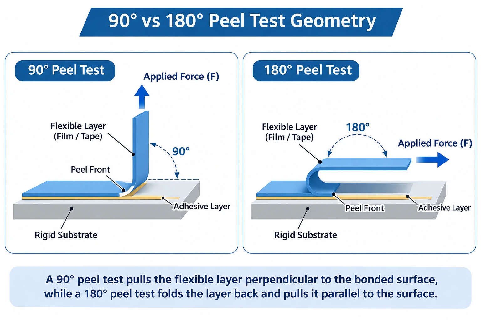
In a 90° peel test, the flexible layer is pulled approximately perpendicular to the bonded surface. In a 180° peel test, the flexible layer is folded back and pulled approximately parallel to that surface.
Neither method is universally better. The correct choice depends on the material structure, applicable test standard, testing objective and fixture configuration.
For testing engineers and equipment buyers, the key questions are:
-
Which peel angle is required for the material?
-
How does the fixture maintain the correct peeling geometry?
-
Why do measured peel forces change with angle?
-
Which ASTM, ISO or IPC test method applies?
-
What testing machine, load cell and fixture configuration is needed?
This guide compares 90° and 180° peel testing from an engineering perspective and explains how to select a suitable peel force testing system.
90° vs 180° Peel Test: Key Differences
Both methods evaluate the resistance to progressive separation of bonded materials. However, their loading arrangements and mechanical responses differ.
| Comparison | 90° Peel Test | 180° Peel Test |
|---|---|---|
| Peel angle | Approximately 90° to the bonded surface | Approximately 180°, with the flexible layer folded back |
| Pulling direction | Perpendicular to the substrate | Approximately parallel to the substrate |
| Fixture arrangement | Often requires controlled substrate movement or guidance | Often uses suitable grips and a fixed substrate arrangement |
| Backing deformation | Flexible layer bends away from the surface | Flexible layer bends back on itself |
| Main setup concern | Maintaining the peel angle as separation progresses | Controlling folding, alignment and backing deformation |
| Example ASTM method | ASTM D3330 Method F | ASTM D3330 Method A |
| Example ISO method | ISO 8510-1 | ISO 8510-2 |
| Result comparison | Method-specific | Not directly interchangeable with 90° results |
A 90° peel test is often used when the specified method requires a flexible material to separate perpendicular to a supported substrate.
A 180° peel test is commonly used when the flexible layer can be folded back without introducing an unacceptable failure mechanism.
Engineering takeaway: Peel force results must be interpreted together with the test angle, specimen geometry, testing conditions and calculation method.
Why Does Peel Angle Affect Peel Force Results?
Peel testing measures the mechanical response of a bonded assembly during separation.
The measured force is influenced by adhesive behavior, material deformation and testing geometry.
Bending of the Flexible Layer
During a 180° peel test, the flexible layer bends back toward the bonded surface.
This bending can contribute to the measured force, particularly when the backing material is relatively stiff.
If the material cracks, yields or undergoes substantial permanent deformation during folding, the result may no longer represent the intended adhesive separation behavior.
Stretching and Deformation
Flexible films, adhesive tapes and polymeric layers may stretch under load.
Part of the applied work may therefore be associated with deformation of the flexible material rather than adhesive separation alone.
This is one reason peel force should not automatically be interpreted as a pure adhesive-interface property.
Adhesive Viscoelasticity
Many adhesive materials respond differently depending on temperature, loading rate and deformation conditions.
A change in test speed or specimen conditioning may alter the measured force even when the nominal peel angle remains unchanged.
For meaningful comparisons, specimen preparation and testing conditions should remain consistent.
Substrate Rigidity
The substrate must be adequately supported for the selected method.
If it bends or rotates during peeling, the actual separation angle may differ from the intended geometry.
This can change the measured force and introduce variability between specimens.
Can 90° and 180° Peel Results Be Compared?
Results obtained at different peel angles can be compared in a controlled engineering investigation, but they should not be treated as interchangeable material properties.
A higher measured force at one angle does not necessarily mean the adhesive bond is intrinsically stronger.
The correct interpretation requires a consistent material system, documented test conditions and an understanding of how geometry affects the result.
How a 90° Peel Test Fixture Works
Maintaining the required angle is one of the most important challenges in 90° peel testing.
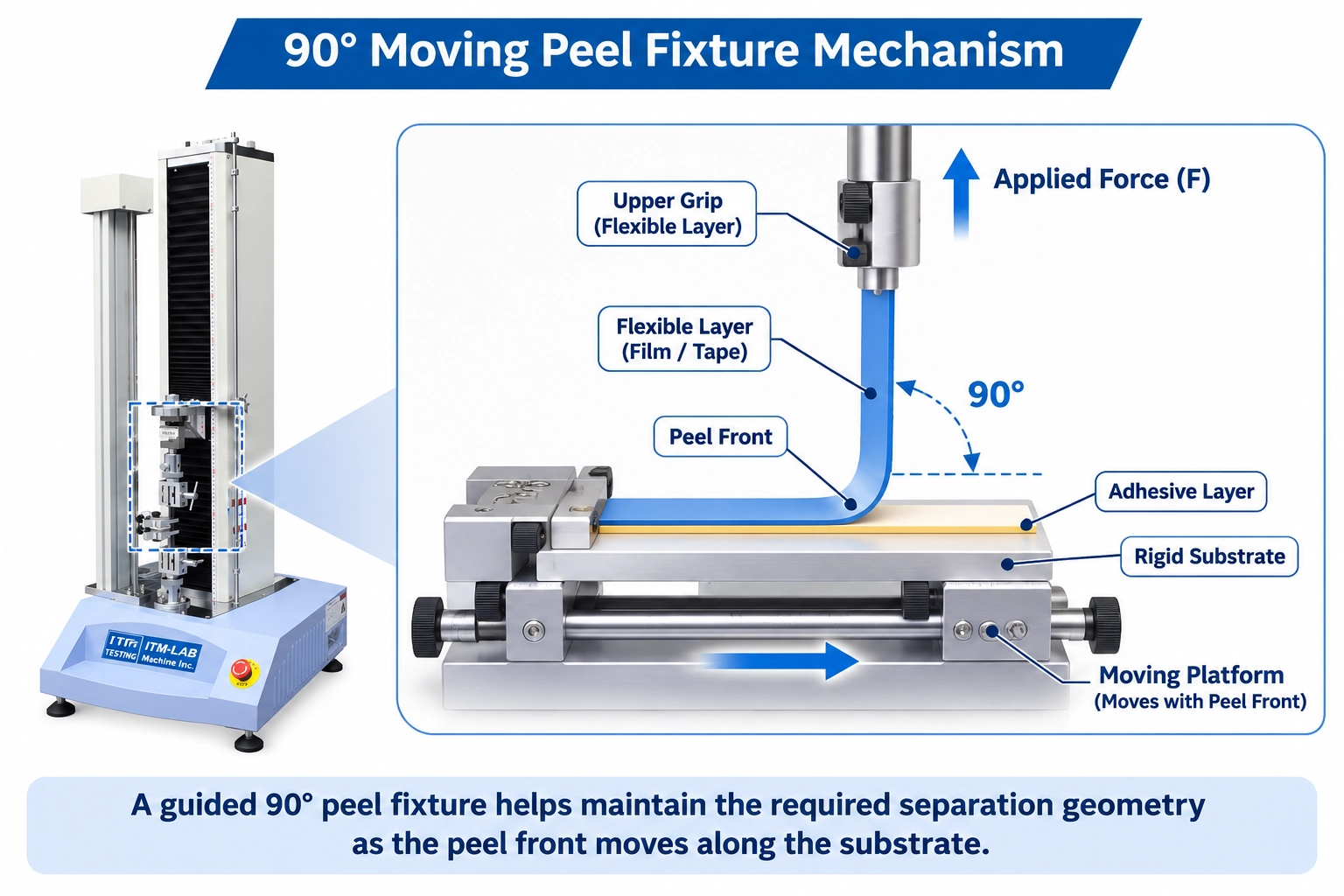
As the flexible layer separates, the peel front moves along the substrate. If the substrate remains fixed while the pulling grip moves, the actual peel angle may change during the test.
Why a Moving Platform Matters
A suitable 90° peel fixture may use a guided or moving substrate platform.
The purpose is to coordinate substrate movement with the separation process so the peeling geometry remains close to the required angle.
The exact mechanism depends on the fixture design and applicable test method.
The critical requirement is not simply that the pulling direction begins at 90°. The angle must remain within the prescribed conditions throughout the relevant test interval.
Key Fixture Requirements
A 90° peel testing configuration should provide:
-
Stable substrate support
-
Controlled peeling geometry
-
Smooth fixture movement
-
Suitable specimen gripping
-
Minimal unintended mechanical resistance
-
Adequate fixture clearance and travel
-
Compatibility with the specified test speed
A moving fixture can introduce resistance of its own. Its design and operation should therefore be considered when evaluating low-force peel measurements.
How to Perform a 180° Peel Test
In a 180° peel test, the flexible layer is folded back and pulled approximately parallel to the bonded surface.
The arrangement may be mechanically simpler than a guided 90° configuration, but specimen preparation and alignment remain essential.
Prepare the Specimen
Prepare the bonded specimen according to the applicable test method.
Important variables may include substrate material, surface treatment, adhesive application, specimen dimensions and conditioning time.
Create a Gripping Tab
Separate enough of the flexible layer to create a suitable gripping section.
Fold the flexible material back without introducing unintended damage.
If the backing cannot tolerate the required bending, another test method may be more appropriate.
Secure the Substrate and Flexible Layer
Position the specimen in the required fixture arrangement.
The grips must prevent slipping without cutting or crushing the material.
Apply the Specified Test Speed
Run the test using the speed and conditions required by the selected standard or customer specification.
Record the force throughout the defined peeling interval.
Evaluate the Results
Depending on the method, the result may involve average force, force per unit width or another specified calculation.
The first peak force should not automatically be used as the reported peel strength.
ASTM, ISO and IPC Standards for 90° and 180° Peel Testing
The ITM-LAB RS-8010A Universal Testing Machine supports 90° and 180° peel testing configurations for a wide range of adhesive materials, films, tapes, laminates and electronic materials.
With suitable peel fixtures, load cells and test settings, the system can be configured for testing applications covered by the following ASTM, ISO and IPC methods.
Peel Test Standards and Applications
| Standard | Test Method / Application |
|---|---|
| ASTM D3330/D3330M | Peel adhesion of pressure-sensitive tapes, including 90° and 180° methods |
| ASTM D903 | Peel or stripping strength of adhesive bonds |
| ASTM D1876 | T-peel resistance of adhesive bonds |
| ISO 8510-1 | 90° peel testing of flexible-to-rigid bonded assemblies |
| ISO 8510-2 | 180° peel testing of flexible-to-rigid bonded assemblies |
| IPC-TM-650 2.4.8 | Peel strength of metallic-clad laminates |
| IPC-TM-650 2.4.8.1 | Metal foil peel strength using the keyhole method |
| IPC-TM-650 2.4.9 | Peel strength of flexible dielectric materials |
ASTM Peel Testing Applications
ASTM D3330/D3330M is commonly used for pressure-sensitive tape adhesion testing.
Method A addresses 180° peel testing, while Method F covers a 90° peel configuration.
ASTM D903 addresses peel or stripping strength of adhesive bonds, while ASTM D1876 covers T-peel resistance.
These methods use different specimen arrangements and should not be treated as interchangeable.
For detailed ASTM D903 and D3330 testing procedures, see ITM-LAB's existing engineering guide:
ASTM D903 & ASTM D3330: Complete Engineering Guide for Peel Adhesion Testing of Adhesives and Tapes
ISO Peel Testing Applications
ISO 8510-1 and ISO 8510-2 cover peel testing of flexible-to-rigid bonded assemblies.
Part 1 addresses 90° peeling, while Part 2 addresses 180° peeling.
The specimen construction, preparation and test apparatus must satisfy the selected method.
IPC Peel Testing for PCB Materials
IPC-TM-650 includes methods for evaluating peel strength in metallic-clad laminates and flexible dielectric materials.
These applications are relevant to PCB laminate manufacturing, flexible circuit materials and electronic material qualification.
Copper foil and flexible circuit laminate testing may require specimen preparation, supporting fixtures and calculation procedures different from those used for ordinary adhesive tapes.
Testing Configurations for Different Standards
ITM-LAB provides 90° and 180° peel fixture options for the RS-8010A.
Additional specimen holders and test configurations can be selected according to the applicable method.
For projects involving adhesive tapes, bonded films, copper-clad laminates or flexible electronic materials, our engineering team can assist with machine and fixture selection based on the required testing procedure.
How to Interpret Peel Force and Peel Strength Results
Peel force data must be evaluated according to the applicable test method.
The highest recorded force is not always the value used to determine the reported peel strength.
Peel Force vs Peel Strength vs Peel Adhesion
Peel force is the measured force required to progressively separate bonded materials under defined conditions.
Peel strength commonly describes resistance to peeling and is often expressed as force per unit specimen width.
Peel adhesion is frequently used in adhesive tape testing to describe adhesion performance measured by a specified peel method.
Terminology and reporting conventions vary between standards.
These terms should not automatically be treated as identical material properties.
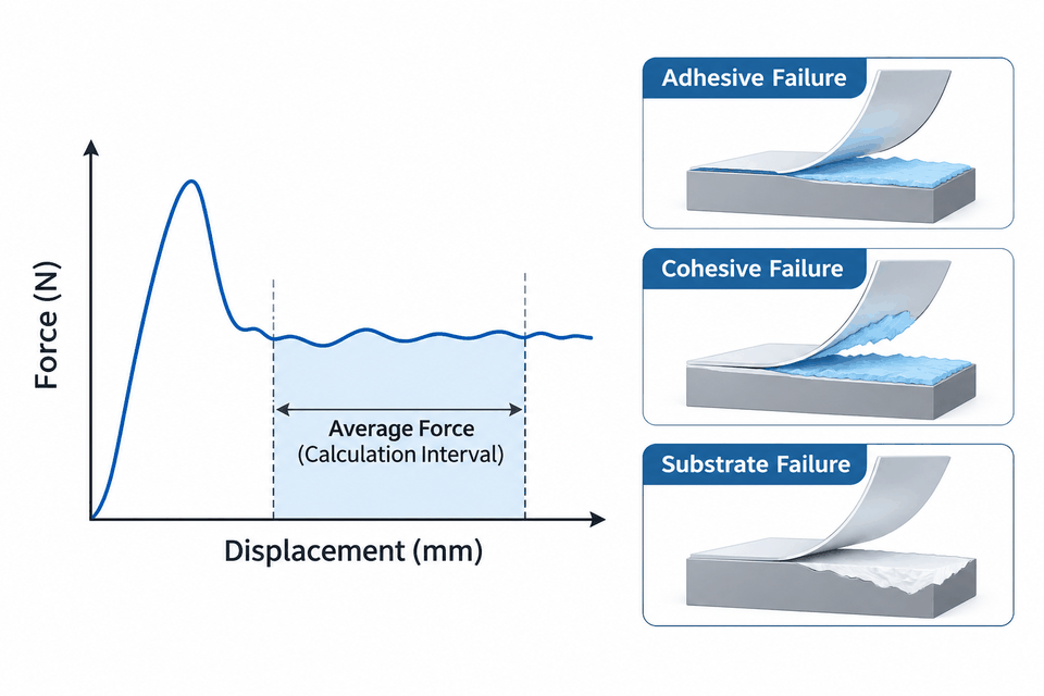
Average Peel Force
Many peel methods require a representative average force over a defined peeling region.
This helps distinguish sustained peeling behavior from initial loading effects or isolated local peaks.
The averaging interval should follow the applicable test method.
Peak Peel Force
Peak force is the maximum recorded force within the selected interval.
It can help identify localized resistance or abnormal behavior, but it is not necessarily the final reported peel strength.
Peel Force per Unit Width
Some methods require force to be normalized by specimen width.
For example, assume an illustrative test produces:
-
Average peel force: 12 N
-
Specimen width: 25 mm
The normalized result is:
12 N ÷ 25 mm = 0.48 N/mm
This calculation is illustrative and does not represent actual ITM-LAB test data.
The reporting unit and calculation procedure must follow the selected standard.
Force–Displacement Curve Interpretation
A peel force curve may show initial loading, progressive separation and local force fluctuations.
The curve can help identify irregular peeling behavior, but it should be interpreted together with specimen observations.
Crosshead displacement is not necessarily identical to the actual movement of the peel front because specimen deformation and fixture movement may contribute.
Common Peel Testing Errors and How to Avoid Them
Even with a suitable testing machine, specimen preparation and fixture conditions can influence the result.
| Testing Issue | Potential Effect | Recommended Check |
|---|---|---|
| Changing peel angle | Alters loading geometry | Verify angle throughout the test |
| Fixture friction | Adds unintended resistance | Check fixture movement |
| Grip slippage | Distorts force and displacement data | Confirm gripping method |
| Backing stretch | Introduces additional deformation | Review material behavior |
| Substrate bending | Changes local peel geometry | Improve specimen support |
| Inconsistent specimen width | Affects normalized results | Record actual dimensions |
| Different conditioning | Changes adhesive response | Follow specified conditioning |
| Incorrect averaging interval | Produces noncomparable results | Use the required calculation region |
Understanding Failure Modes
Adhesive failure: Separation occurs at the adhesive–substrate interface.
Cohesive failure: Separation occurs within the adhesive material.
Substrate failure: The film, foil or other adherend tears or fractures.
Mixed failure: Multiple failure mechanisms occur within the same specimen.
Failure observations should be included in the test report because a force value alone does not explain how the bonded assembly failed.
How to Select a Peel Force Testing Machine
The best peel testing machine is not necessarily the one with the highest force capacity.
A suitable system must reproduce the required test geometry and measure force accurately within the expected working range.
Start with the Material and Test Standard
Identify the material structure, required peel angle and applicable standard.
The selected method determines the specimen preparation, fixture requirements, test speed and reporting format.
Select the Peel Fixture
Choose a fixture that supports the required angle and specimen geometry.
A 90° configuration may require controlled platform movement, while a 180° configuration requires suitable grips and sufficient space for the folded backing.
Specialized IPC methods may require additional fixture designs.
Select the Load Cell
Choose a load cell with a verified measurement range suitable for the expected peel force.
The machine's maximum capacity does not determine its accuracy at every lower force.
Verify Speed and Travel
Confirm that the machine can operate at the prescribed test speed.
Check the usable travel after the specimen and fixture have been installed.
Confirm Data and Reporting Requirements
Determine whether the project requires:
-
Force–displacement curves
-
Average peel force
-
Peak peel force
-
Force per unit width
-
Defined analysis intervals
-
Exportable test reports
The required calculations and software functions should be verified for the proposed configuration.
Peel Test Equipment Selection Roadmap
DEFINE THE MATERIAL AND STANDARD
↓
SELECT THE REQUIRED PEEL ANGLE
↓
VERIFY THE 90° OR 180° FIXTURE
↓
SELECT THE APPROPRIATE LOAD CELL
↓
CHECK SPEED, TRAVEL AND SOFTWARE
↓
CONFIRM THE CONFIGURATION WITH A REPRESENTATIVE SAMPLE
This approach helps avoid selecting a machine based only on its published maximum capacity.
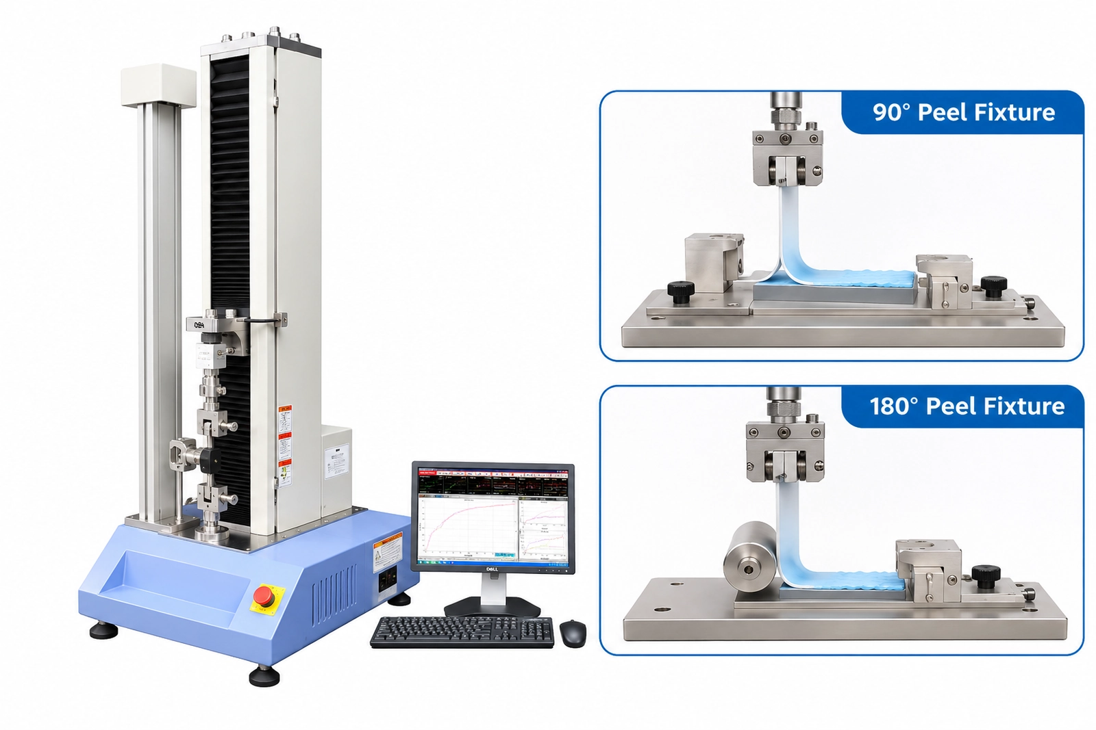
ITM-LAB RS-8010A: 90° and 180° Peel Test Configurations
The ITM-LAB RS-8010A Universal Testing Machine is a servo-controlled testing platform that can be configured for tensile, compression and selected peel force applications.
For peel testing, ITM-LAB provides 90° and 180° peel fixture configurations.
The appropriate arrangement depends on the specimen, required test method and expected force range.
RS-8010A Technical Specifications
| Parameter | RS-8010A |
|---|---|
| Available force capacities | 50 N–5 kN |
| Test speed | 0.001–500 mm/min |
| Force accuracy | ±0.25% of indicated value within the specified range |
| Available stroke configurations | 650 / 1000 mm |
| Peel fixture options | 90° and 180° |
| Configuration basis | Material, standard, force range and test geometry |
90° Peel Test Configuration
RS-8010A Universal Testing Machine
Suitable Load Cell
90° Peel Fixture
Test Software and Reporting Configuration
180° Peel Test Configuration
RS-8010A Universal Testing Machine
Suitable Load Cell
180° Peel Fixture
Test Software and Reporting Configuration
These are example configurations. The final system should be selected according to the applicable test method and specimen requirements.
What Should Be Confirmed Before Ordering?
Before selecting the final system, engineers should verify:
-
Material and specimen dimensions
-
Applicable ASTM, ISO, IPC or customer method
-
Required peel angle and fixture geometry
-
Expected force and measurement range
-
Test speed and usable travel
-
Software calculations and reporting requirements
-
Any specialized specimen preparation or apparatus requirements
ITM-LAB can review the proposed configuration against the testing requirements and recommend suitable machine and fixture options.
Frequently Asked Questions
- Can 90° and 180° peel test results be directly compared?
Not as interchangeable material properties. Different peeling geometries affect backing deformation and measured force. Comparisons should account for test angle, specimen construction, speed and method.
- Does ASTM D3330 require a special 90° peel fixture?
ASTM D3330 Method F requires a suitable 90° peel arrangement. The apparatus must maintain the prescribed geometry during testing, which may require a guided or moving substrate fixture.
- Can one universal testing machine perform both 90° and 180° peel tests?
Yes. A universal testing machine can support both methods when equipped with appropriate fixtures, a suitable load cell and the required test-control capabilities.
- What load cell is suitable for low-force peel testing?
The load cell should be selected according to the expected peel force and the verified measurement performance of the proposed system. Maximum machine capacity alone is not sufficient.
- Can the RS-8010A support IPC-TM-650 peel test methods?
The RS-8010A can be configured for relevant peel testing applications. For IPC-TM-650 methods, the exact specimen arrangement, fixture geometry, force measurement and reporting requirements should be matched to the selected procedure.
- What information should I provide when requesting a peel testing machine?
Provide the specimen material, dimensions, required peel angle, applicable standard, expected force, test speed and reporting requirements. A specimen photograph or drawing can help determine the suitable fixture.
Request a Peel Test Configuration for Your Material and Standard
Choosing between 90° and 180° peel testing starts with understanding the bonded material and required test method.
ITM-LAB can review your application and recommend a suitable RS-8010A machine and peel fixture configuration.
Please provide:
-
Material or bonded assembly description
-
Specimen width, length and thickness
-
Required 90° or 180° peel angle
-
Applicable ASTM, ISO, IPC or customer standard
-
Expected peel force and required test speed
-
Reporting requirements and acceptance criteria
Get a Peel Test Machine & Fixture Configuration
ITM-LAB Testing Machine Inc.
Manufacturer of Material and Reliability Testing Equipment
Related Resources
