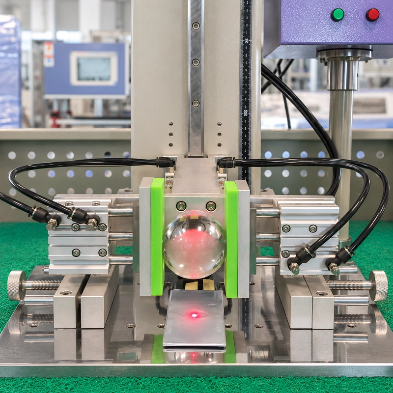
Steel ball impact testing applies a localized impact to a selected position on a battery cell using a ball released from a defined height. The test arrangement should specify the ball mass and diameter, release height, impact location, specimen support and evaluation criteria.
For blade battery cells, equipment selection starts with the actual specimen and test requirements. Cell dimensions, orientation and support conditions determine whether the machine and fixture can reproduce the intended loading arrangement.
This guide uses an ITM-LAB RS-8220V-XY blade battery testing demonstration to explain the setup and the information needed for equipment selection. The machine is identified as RS-8220V in the demonstration video.
Have a cell drawing or an existing test procedure? Send your requirements to ITM-LAB for a configuration review.
What Does a Steel Ball Impact Test Evaluate?
A steel ball impact test can help examine a battery cell’s response to a specified localized impact during product development or engineering evaluation.
The test objective determines what must be recorded. An evaluation focused on external mechanical damage may examine indentation and changes in cell shape. An investigation of electrical or thermal response also requires suitable measurements and a defined observation period.
The equipment settings alone do not establish whether a specimen passes. Acceptance criteria must come from the applicable test procedure or agreed engineering requirements.
For an introduction to falling-ball methods and equipment types, see our Steel Ball Drop Test: Standards, Applications and Equipment Selection Guide.
Blade Battery Testing with the RS-8220V-XY
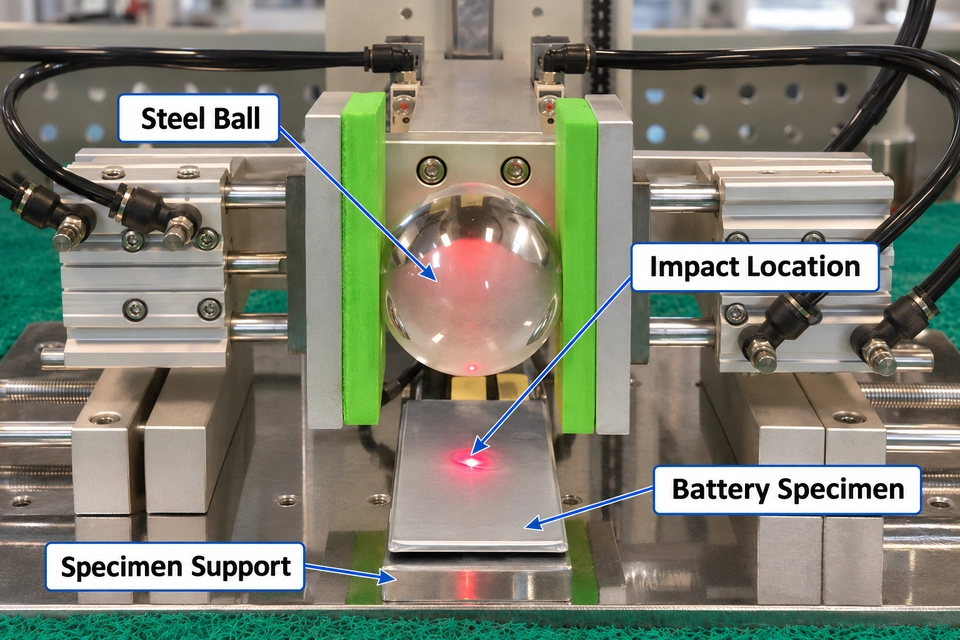
The ITM-LAB demonstration shows a steel ball positioned above a supported battery specimen. The footage includes the ball-handling arrangement, vertical movement, release sequence and touchscreen interface.
A red laser spot is visible in the specimen area, providing a visual reference for impact-point alignment.
These visible elements help explain how the equipment is arranged for the application:
| Visible Element | What to Review for Your Application |
|---|---|
| Battery specimen beneath the ball | Whether the required cell orientation and impact surface can be accommodated |
| Specimen support | Whether the support arrangement matches the test procedure |
| Ball-handling mechanism | Compatibility with the specified ball and release sequence |
| Laser reference | How the intended impact location is identified before release |
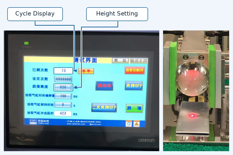
| Touchscreen interface | How settings and cycle information are displayed |
The demonstration documents equipment operation. Evaluating battery performance also requires the associated specimen information, test conditions, observations and acceptance criteria.
Define the Specimen Support Before Testing
The support arrangement is part of the test condition. A cell supported across its lower surface can respond differently from one supported at selected locations.
Before configuring the fixture, identify how the test procedure requires the cell to be supported. Record the support dimensions, contact locations and any material placed between the cell and support.
The fixture should locate the specimen consistently without introducing unintended restraint or loading. Document its relationship to the impact point so that the arrangement can be reproduced.
For elongated cells, check the available space around the specimen as well as beneath the ball. The cell body, terminals, fixture and any measurement leads must fit within the proposed arrangement.
A configuration review should address:
- Cell length, width and thickness.
- Intended impact surface and specimen orientation.
- Support contact locations and dimensions.
- Required restraint and permitted specimen movement.
- Clearance for terminals, leads and surrounding components.
A drawing or photograph of the intended support arrangement helps establish these requirements before equipment selection.
Identify the Impact Point from a Fixed Reference
Describe the impact location using a drawing, photograph or coordinates measured from an identifiable cell feature.
“Near the center” can be interpreted differently by different operators. A location referenced to the cell edges or a defined datum is easier to reproduce.
Where several positions are required, assign a point ID to each location. Record the specimen orientation alongside that ID so that a change in impact location can be distinguished from a change in how the cell was installed.
Laser alignment can help an operator locate the intended point. The test record should still identify the target position and the method used to establish it.
Specify the Ball, Release Height and Impact Sequence
Ball mass, ball diameter and release height should be specified together. Ball diameter affects the contact geometry, while mass and height contribute to the theoretical energy available before impact.
For a gravity-driven drop, theoretical potential energy can be estimated using:
E = mgh
Where:
- E is theoretical potential energy in joules.
- m is ball mass in kilograms.
- g is gravitational acceleration, approximately 9.81 m/s².
- h is the defined vertical drop distance in meters.
This calculation does not directly measure impact force or energy absorbed by the battery cell.
Define the Height Measurement Reference
Record the reference points used to establish the drop distance and check how they relate to the machine’s height setting.
Where the method defines height as the distance from the lowest point of the ball to the impact surface, use that reference consistently. If the governing procedure specifies another reference, follow that procedure.
A controller display forms one part of the record. Ball identification, specimen position and the height measurement reference are also needed to document the test condition.
Assign Impacts to the Correct Specimen
The required number of impacts should be assigned to a specific specimen and impact location.
Distinguish the machine’s accumulated cycle count from the number of impacts applied to one cell. The specimen record should show which cell received each impact and whether a fresh specimen was used.
Repeated impacts may change the specimen’s condition. The test procedure should define whether repeated impacts at the same location are permitted.
What Should Be Recorded After Impact?
Establish the inspection plan before testing. This makes the recorded observations relevant to the test objective and allows specimens to be compared under consistent conditions.
| Record Category | Information to Document |
|---|---|
| Specimen identification | Cell ID, dimensions, orientation and relevant pre-test condition |
| Impact conditions | Ball identification, mass, diameter, height reference and impact-point ID |
| Support arrangement | Fixture identification, support contacts and installation photograph |
| External condition | Location and extent of indentation, deformation or other visible changes |
| Electrical observations | Measurements required by the test plan, where applicable |
| Thermal observations | Measurements and observation period required by the test plan |
| Evaluation | Result against the specified acceptance criteria |
Take before-and-after photographs from comparable angles. Include an overall view and a closer view of the impact area, with a scale where dimensions need to be assessed.
Visible appearance provides one part of the evaluation. Where the objective concerns internal damage or electrical behavior, the assessment needs the corresponding measurements or examination methods.
For energized-cell testing, the laboratory plan should also define cell preparation, monitoring, containment and post-test handling. Review these requirements when configuring the equipment installation.
How Does Steel Ball Impact Differ from Other Battery Mechanical Tests?
“Battery impact testing” can refer to several loading arrangements. Identify the required method before selecting equipment.
| Test Arrangement | How the Load Is Applied | Main Selection Considerations |
|---|---|---|
| Direct steel ball impact | A released ball strikes a selected specimen location | Ball geometry, release height, impact alignment and specimen support |
| Falling-weight and bar impact | A falling mass transfers load through a bar placed across the specimen | Specified mass, bar geometry, support and method applicability |
| Crush testing | Compression is applied through defined contact surfaces | Loading geometry, force or displacement control and stopping criteria |
These arrangements create different loading conditions. Select the equipment against the actual test procedure.
The UN Manual of Tests and Criteria includes an impact/crush test in subsection 38.3, with method applicability linked to cell type. A direct steel ball demonstration does not establish completion of the applicable UN 38.3 procedure. Consult the governing edition and amendments when defining a compliance program.
Reference: UNECE — UN Manual of Tests and Criteria, Revision 8 and Amendment 1.
Selecting an RS-8220V-XY Configuration
The ITM-LAB RS-8220V-XY Auto Steel Ball Impact Tester, identified as RS-8220V in the demonstration video, is shown here in a blade battery cell testing application.
Start with the required test arrangement, then check the machine and fixture against it. Confirm ball compatibility, usable specimen space, positioning requirements and the intended support arrangement.
For an initial configuration review, provide the following information:
| Information to Provide | Why It Matters |
|---|---|
| Cell drawing and dimensions | Establishes specimen fit, orientation and fixture space |
| Impact-point drawing | Defines alignment and positioning requirements |
| Ball mass and diameter | Establishes ball-handling and contact requirements |
| Release height and measurement reference | Defines the required vertical arrangement |
| Support or restraint method | Establishes the fixture design |
| Impacts per specimen | Defines the planned test sequence |
| Monitoring requirements | Identifies any measurement and data-acquisition needs |
| Laboratory protection requirements | Supports review of the installation arrangement |
| Acceptance criteria | Defines how the test outcome will be evaluated |
Request a blade battery impact test configuration review.
Send your cell drawing, impact locations and test requirements so ITM-LAB can review the proposed machine and fixture configuration.
Frequently Asked Questions
Can a steel ball impact tester be used for blade battery cells?
It may be suitable for a defined localized-impact evaluation when the machine, ball, fixture and laboratory installation match the test plan. Check suitability against the actual cell dimensions and required loading conditions.
What ball mass and drop height should be used?
Use the values specified by the applicable procedure or approved engineering test plan. The demonstration does not establish a universal ball mass or release height for blade battery cells.
Does the demonstration show that the battery cell passed?
The video shows equipment operation and the specimen arrangement. A pass result requires documented test conditions, observations and acceptance criteria.
Does the machine measure impact force?
The demonstration does not establish instrumented impact-force measurement. If force-time data is required, specify it separately and confirm the sensing and data-acquisition configuration.
Can the same cell receive repeated impacts?
Follow the governing test procedure. Record impacts by specimen and location, and distinguish them from the machine’s accumulated cycle count.
What should I send when requesting a quotation?
Send the cell drawing, impact locations, ball requirements, release height, support method and evaluation criteria. Include any monitoring and laboratory protection requirements for the configuration review.