
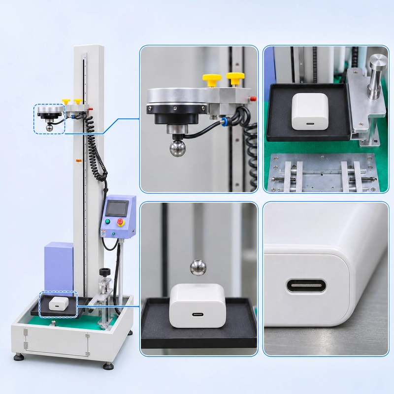
A steel ball impact test checks how an electronic housing responds to a strike at a defined location. Choose the impact points and specimen support, then use the ball size, mass and drop height specified in the test procedure. After impact, inspect both the strike area and the corresponding internal features where accessible.
A broad plastic panel may dent or bow. The edge of a USB‑C opening may crack. A strike near a seam may leave little visible damage at the impact point while the joint opens or shifts. A useful test plan specifies where to strike, how to support the housing and what to inspect afterward.
Where Should You Strike an Electronic Housing?
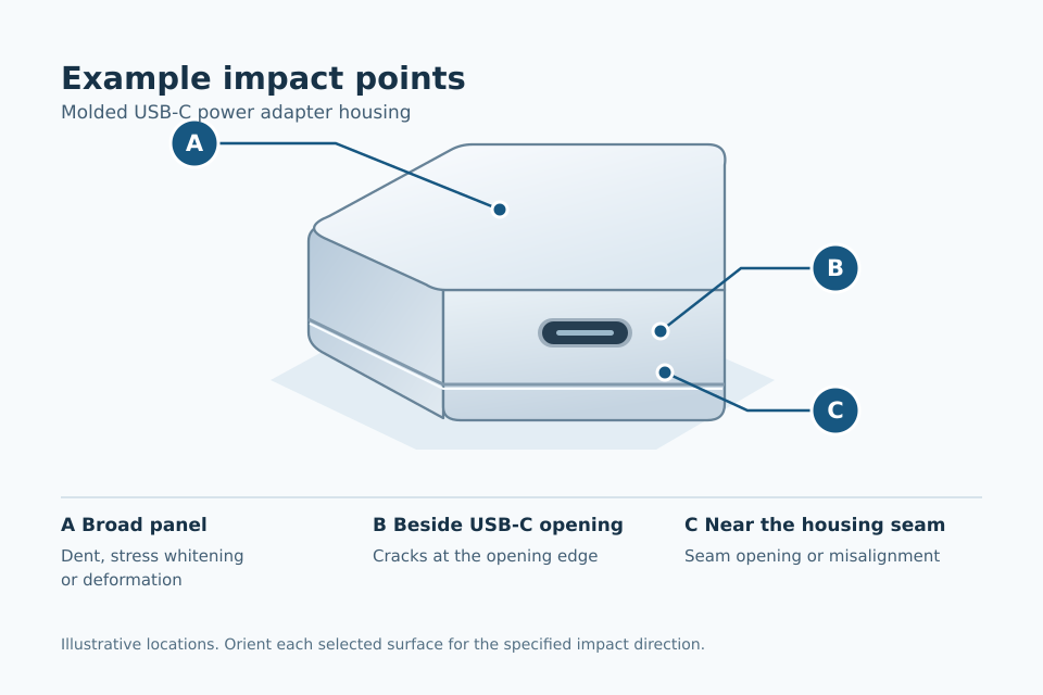
Use the impact locations specified by the applicable procedure or customer requirements. For an internal design comparison, choose points based on the failure modes you want to investigate. Mark each point on a drawing or photograph using a feature the operator can locate again, such as the edge of a connector opening.
A molded USB‑C power adapter housing illustrates three common choices. Test each selected surface in the orientation required by the procedure. For a vertical ball drop, position the intended strike surface facing upward.
| Candidate impact point | Why test here? | What to check outside | What to check inside |
|---|---|---|---|
| A. Broad housing panel | Evaluate how a panel bends between supports. | Local indentation, permanent bowing, stress whitening or cracks. | Cracks or whitening near the ribs or supports behind the strike area, where present. |
| B. Plastic beside the USB‑C opening | Evaluate the narrow section around the cutout. Record the target’s offset from the opening edge. | Cracks starting at the edge, distortion of the opening or whitening around the strike. | Damage to adjacent supports or retainers. Check connector movement if the assembled sample and test plan call for it. |
| C. Plastic near the housing seam | Check whether the joint stays aligned after a nearby strike. Mark the target on the chosen side of the seam. | Seam opening, a step between the housing halves or local cracking. | Damage to the joint or retention features, where present and accessible. |
Should You Test the Empty Shell or the Assembled Housing?
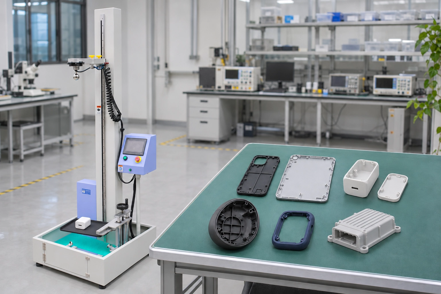
Use an empty shell when comparing shell materials or molded geometries under the same support conditions. Record which half you tested, which surface faced the ball and where the fixture contacted the part. If you are comparing two designs around a USB‑C opening, keep the support, ball, drop height and target location consistent.
Use an assembled housing when the test is intended to show how the housing halves, joint, fasteners or internal supports behave together. Record what was installed and how it was secured. If you use a dummy insert, document where it contacts the housing. For qualification testing, follow the assembly condition specified in the governing procedure.
How Should You Support and Align the Specimen?
Start by identifying what supports the housing during impact. A support pad directly beneath the strike area can limit panel movement and change the result. If the method specifies fixture contact points or restraints, reproduce them. For an internal comparison, document the setup and keep it consistent across specimens.
- Set the orientation and support. Seat the housing on the intended supports. Photograph or sketch the contact points, restraints and clearance beneath the target.
- Confirm the ball and height reference. Record the ball mass and diameter. Measure the drop height from the reference specified in the procedure. Recheck it when rotating the housing changes the height of the strike surface.
- Align the target. Match the marked point on the housing to the test drawing. Use laser-assisted positioning where available, then verify the actual strike location as required by the test method.
- Record the impact sequence. Document the number of strikes per location and whether the specimen is reused. Use separate undamaged specimens when the objective is to isolate damage at each point and the procedure permits it. If a single strike is required, record any unintended second contact.
For the USB‑C adapter example, switching from A on the broad panel to B beside the connector opening changes the specimen orientation. Record the new support contacts and recheck the height reference before releasing the ball.
What Should You Inspect After the Impact?
Photograph the strike area and the assembled housing before opening it. Compare the surface, connector opening and seam with their pre-test condition. If the procedure permits disassembly, inspect the internal features corresponding to the strike, such as ribs, clips, joint surfaces or screw bosses.
Record the observation before assigning pass or fail. For example, “Visible crack starting at the USB‑C opening edge” identifies what happened and where. Then apply the acceptance criteria in the test procedure. If the plan also requires a connector-fit or functional check, record it separately from the visual findings.
| Record field | What to capture |
|---|---|
| Specimen and assembly state | Sample ID, housing revision, tested half or assembly condition, and internal components relevant to the test. |
| Orientation and support | Surface facing the ball, fixture contact locations, restraints and clearance beneath the target. |
| Ball and drop height | Ball mass, diameter, drop height and the reference used to measure it. |
| Impact point and sequence | Target ID, actual strike location if verified, number of strikes and any unintended additional contact. |
| Observations and result | External and internal findings where inspected, photo references, required functional checks and pass/fail against the specified criterion. |
Using the RS‑8220G for Localized Steel Ball Impact Testing
The ITM‑LAB RS‑8220G provides vertical steel ball release, an adjustable drop height of 200–1800 mm and laser-assisted impact positioning. Confirm the usable drop height with your specimen and fixture installed. The RS‑8220G requires a mechanical clamping fixture for balls over 200 g. View the RS‑8220G steel ball impact tester
Equipment Supplied to OPPO and Foxconn
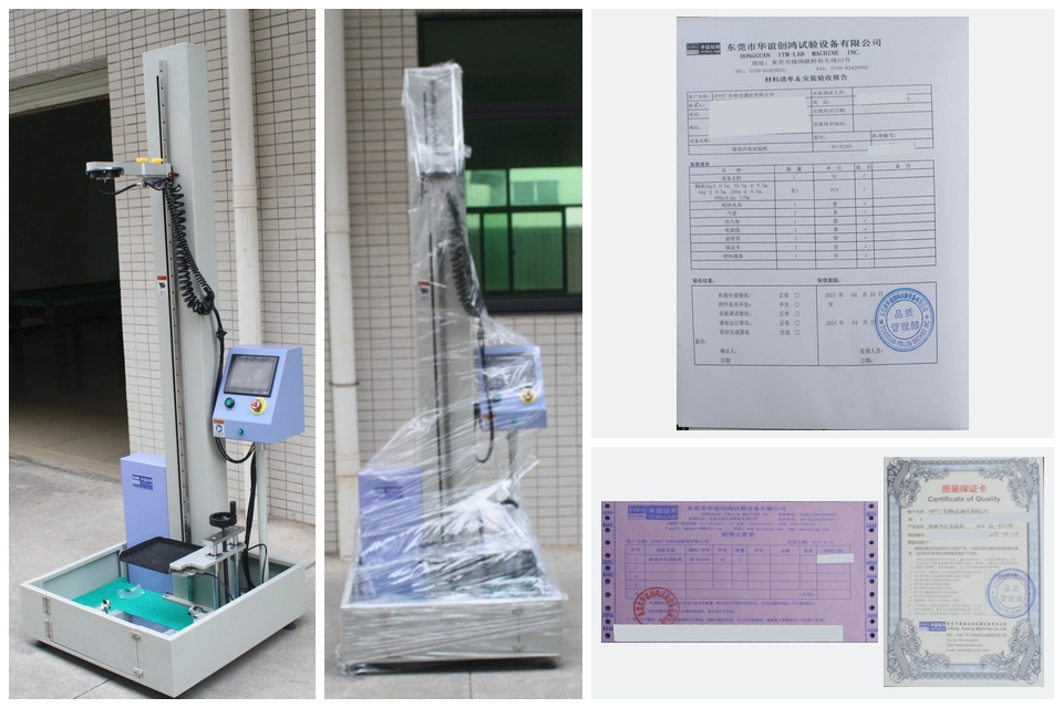
ITM‑LAB has supplied impact testing equipment to OPPO and Foxconn. In April 2023, ITM‑LAB shipped one RS‑8220G steel ball impact tester to OPPO. The pre-shipment photo shows the machine’s vertical column, control panel and test platform.
For other applications, see the steel ball drop test guide. If your objective is to evaluate what happens when the entire adapter falls, see the charger drop test guide.
Frequently Asked Questions
Will the same ball and drop height cause the same damage at every point?
Damage can vary because the wall geometry, joint design and support differ across the housing. Record the target location and support conditions even when the ball and drop height are the same.
Can I use one housing for all three impact points?
Follow the test procedure. For independent comparisons, separate undamaged specimens help isolate the effect of each strike. If the procedure calls for multiple strikes on one housing, record their order and the condition of the specimen between strikes.
Is a visual inspection enough to determine whether the housing passed?
That depends on the acceptance criteria. A visual inspection can document cracking, deformation or seam movement. Some test plans also require a check of connector fit, joint retention, product function or safety.
Planning a steel ball impact test for your housing? Send ITM‑LAB your specimen drawing, required strike points and test procedure so we can review the fixture and equipment configuration. Contact ITM‑LAB
