
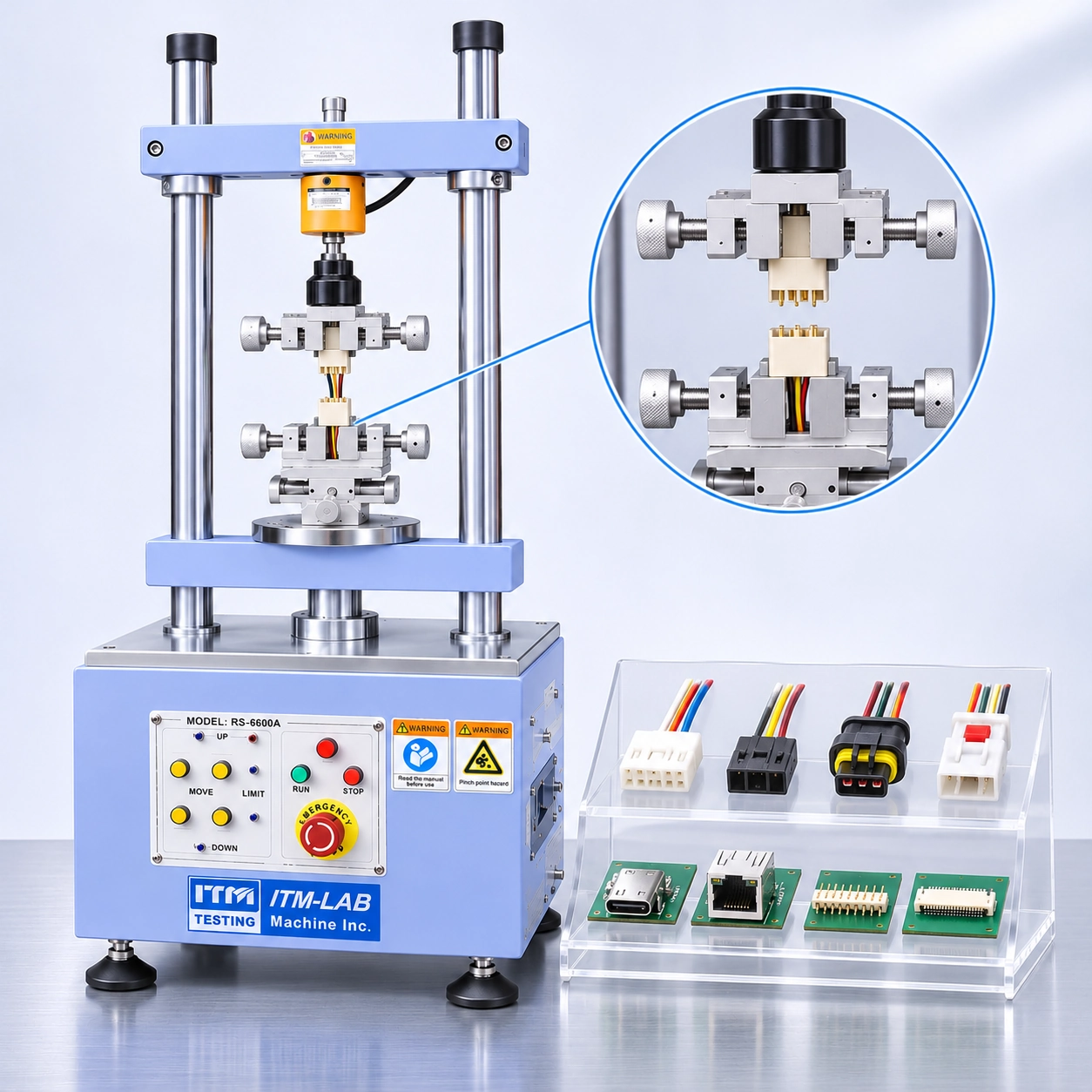
What Makes a Reliable Connector Test Fixture?
A connector test fixture must securely hold both mating halves, maintain the specified mating axis, and allow the required insertion or extraction movement without unintended interference. The fixture should reproduce the mounting conditions defined by the test method while preventing housing deformation, specimen movement, and unwanted side loading.
Even a force tester with sufficient capacity and travel can produce misleading results when the connector is mounted incorrectly.
For complete connector assemblies, the measured force may involve multiple terminals, housing guides, seals, and locking features. The fixture must allow these interactions to occur under the intended test conditions.
The real question is not whether a connector fits between two grips. It is whether the connector can complete its specified mating movement without the fixture changing the mechanical event being measured.
What Must the Fixture Control?
| Requirement | Why It Matters |
|---|---|
| Specimen mounting | Prevents movement and unintended deformation |
| Mating-axis alignment | Reduces unwanted lateral loading |
| Housing support | Maintains the required mounting condition |
| Functional clearance | Avoids interference with seals, latches, and guides |
| Usable travel | Allows the complete specified movement |
| Setup repeatability | Supports consistent measurements across tests |
A suitable fixture is therefore part of the measurement system, not simply an accessory attached to the machine.
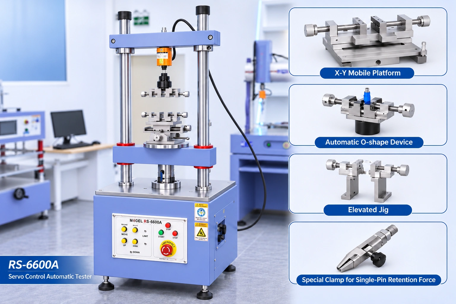
How Should Upper and Lower Connector Fixtures Be Configured?
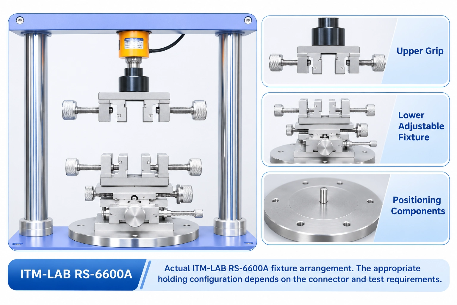
A vertical connector force tester typically uses an upper fixture connected to the moving force measurement assembly and a lower fixture mounted on a fixed or adjustable support.
Each fixture holds one half of the mating connector pair.
The plug does not always belong in the upper fixture, nor must the receptacle always be positioned below. The correct arrangement depends on the connector geometry, installation requirements, and applicable test method.
Upper Fixture: Secure Holding Without Deformation
The upper fixture transfers the applied load to the moving connector half.
Its design should consider the available gripping surfaces, housing stiffness, load direction, and clearance around functional features.
A small connector may have an accessible plastic wall that appears suitable for clamping. If that wall is thin or unsupported, however, tightening the grip can distort the housing before the test begins.
The resulting force measurement may then include resistance associated with the mounting condition.
Where direct gripping is unsuitable, a dedicated holder or shaped locating component may provide better support.
Lower Fixture: Establishing the Mounting Datum
The lower fixture positions the opposing connector half relative to the movement axis.
It may incorporate standard grips, adjustable positioning components, or a dedicated locating nest.
The mounting datum—the surface or feature used to establish the specimen's position—should reflect the required test condition.
For a panel-mounted connector, the panel interface may be more relevant than an arbitrary housing surface. For a PCB-mounted header, the board and its support may need to be included in the test setup.
The fixture should not transfer the measurement load through an unintended flexible feature.
Fixture Configuration by Connector Geometry
| Connector Configuration | Typical Fixture Approach | Critical Check |
|---|---|---|
| Inline plug and receptacle | Opposing housing grips or dedicated holders | Axial alignment |
| PCB-mounted header | Connector holder with supported PCB fixture | Board deflection |
| Board-to-board connector | Supported board assemblies | Parallelism and alignment |
| Sealed automotive connector | Housing support with functional clearance | Seal and latch interference |
| Multi-pin connector | Stable full-housing support | Uneven engagement |
| Compact electronic connector | Precision locating fixture | Housing deformation |
These are illustrative configurations. Actual upper and lower mounting positions may be reversed according to the approved procedure.
How Does an X-Y Adjustable Platform Help Align the Connector?
An X-Y adjustable platform allows the relative horizontal position of the mating connector halves to be adjusted before testing.
On the ITM-LAB RS-6600A, the adjustable lower fixture arrangement can assist with positioning the connector interface.
However, positional adjustment is not the same as automatic correction of every alignment error.
A connector may appear centered from the front while approaching its mating half at a slight angle. The problem may only become apparent when the first guiding surfaces make contact.
What Happens When the Mating Axes Are Offset?
A lateral offset can cause premature contact between housing surfaces.
An angular offset may lead to uneven engagement and additional resistance during insertion.
The force sensor may then record mechanical resistance that does not belong to the intended test condition.
Possible symptoms include an early force rise, an irregular local peak, or inconsistent results between repeated tests.
These symptoms are not conclusive proof of fixture misalignment. Connector defects and dimensional variation can produce similar effects.
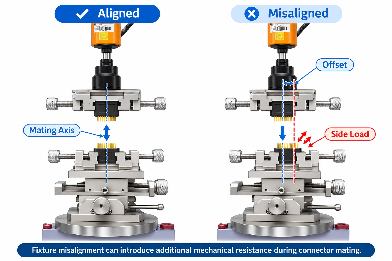
Before recording test data, verify the connector orientation, fixture mounting surfaces, available movement, and absence of unintended contact.
Where permitted by the test procedure, a controlled setup movement can help reveal interference.
A repeatable result is not necessarily a valid result if the fixture repeatedly reproduces the wrong mating geometry.
Standard or Custom Connector Test Fixture: Which Do You Need?
Standard gripping fixtures may be sufficient when the connector has accessible, mechanically robust holding surfaces.
Other specimens require adjustable positioning, additional clearance, or dedicated mounting components.
The decision should be based on the specimen's geometry and required test condition rather than the assumption that a more complex fixture is always better.
| Fixture Type | Suitable Application | Main Consideration |
|---|---|---|
| Standard gripping fixture | Simple connector housings | Clamping security and deformation |
| X-Y adjustable fixture | Position-sensitive mating interfaces | Alignment and locking stability |
| Elevated fixture | Tall specimens or special mounting geometry | Remaining clearance and rigidity |
| Dedicated connector nest | Defined housing geometry | Repeatable locating datum |
| Custom connector fixture | Irregular or sensitive connector structures | Correct load path and validation |
| Controlled floating fixture | Applications permitting specified compliance | Uncontrolled movement |
When Is a Custom Fixture Necessary?
A custom connector test fixture should be considered when standard grips cannot reproduce the required mounting condition.
Typical reasons include limited gripping surfaces, irregular housing geometry, sensitive locking mechanisms, integrated mounting flanges, or restricted access around the mating interface.
A PCB-mounted header, for example, may require a fixture that supports the board rather than directly gripping the connector housing.
A sealed connector may require dedicated clearance around its latch and sealing features.
The purpose of customization is to control the test boundary—not simply to accommodate an unusual shape.
Three Practical Configuration Examples
Compact Inline Connector
Where the housing has suitable gripping surfaces and the latch remains unobstructed, standard upper and lower grips may be adequate after alignment and clamping checks.
PCB-Mounted Connector
When the approved test condition includes the mounted assembly, a dedicated PCB support may be necessary to avoid unintended board movement or bending.
Sealed Multi-Pin Connector
The fixture must hold the housing securely while allowing seals, guides, and locking features to operate under the defined test condition.
These examples illustrate engineering decisions rather than completed customer projects.
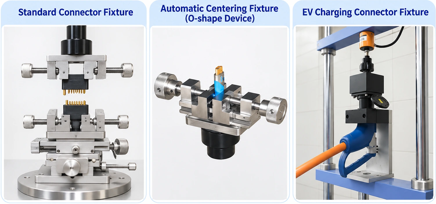
Rigid Mounting vs Controlled Floating
A rigid fixture holds the specimen in a defined position and orientation. This may be appropriate when the test method requires controlled axial movement with limited lateral freedom.
A controlled floating arrangement permits specified movement or compliance.
Neither approach is universally correct.
An overly constrained fixture can introduce resistance if it prevents the connector from following guidance features that are intended to operate during mating.
Excessive freedom can also change the test condition by allowing uncontrolled movement.
Before selecting a floating arrangement, the engineer should establish which degrees of freedom are permitted, how much movement is acceptable, and whether that movement reflects the intended installation condition.
Floating should not be used to conceal incorrect initial alignment.
Preventing Housing, Latch, and Seal Interference
A connector can be held securely and still be mounted incorrectly.
This occurs when the fixture contacts or preloads a feature that should remain free during mating or unmating.
Housing Support
Clamping pressure should be applied through suitable structural surfaces. A shaped locating nest may provide more consistent support than a narrow grip contacting an unsupported plastic wall.
Latch and Lock Clearance
The fixture must not unintentionally release, block, or preload a locking mechanism.
For unmating measurements, the latch condition must be defined in advance. Separation with the latch released is a different mechanical event from applying a separating load while the latch remains engaged.
Seal and Guidance Clearance
For sealed connectors, the fixture should allow the intended sealing and guiding surfaces to engage naturally.
It should not compress a seal or obstruct the connector's specified mating movement.
The goal is to measure the connector under its intended condition, not create a different condition through the fixture.
How Fixture Errors Affect Force–Displacement Results
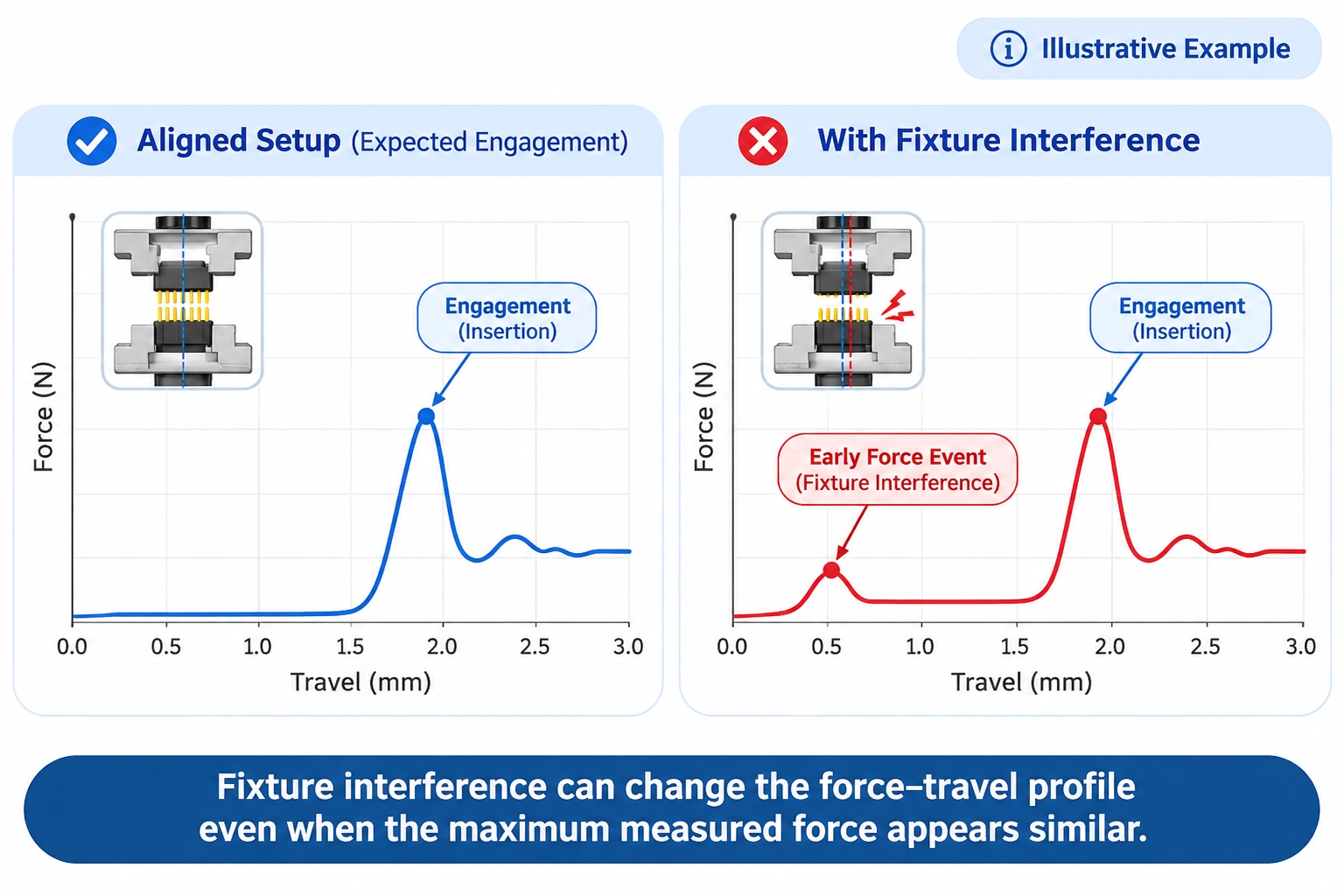
A force–displacement curve records the measured force throughout the connector's defined movement.
It can help locate an unexpected mechanical event, although the curve alone cannot establish its cause.
Consider two illustrative tests performed on the same connector.
With a correctly aligned fixture, the connector follows its intended mating path and produces a representative engagement curve.
With an offset fixture, premature housing contact may create an additional force event earlier in the travel.
The two tests could produce similar maximum forces while representing different mechanical behavior.
Common Fixture-Related Measurement Problems
| Observed Result | Possible Fixture Cause | Recommended Check |
|---|---|---|
| Early force rise | Premature housing contact | Initial alignment |
| Inconsistent peak force | Specimen movement | Grip security |
| Irregular force curve | Binding or intermittent interference | Complete mating path |
| Unexpectedly high force | Side loading or housing deformation | Alignment and clamping |
| Incomplete mating | Insufficient clearance | Usable travel and endpoint |
| Results drift during repeated tests | Fixture loosening or position change | Mounting stability |
These are diagnostic possibilities, not definitive conclusions.
Connector defects, tolerance variation, and other mechanical conditions may produce similar results. The specimen, fixture, and test method should all be reviewed before identifying the root cause.
Check Usable Travel Before Approving the Fixture
The rated travel of a force tester does not automatically equal the usable mating travel available after installing the specimen and fixtures.
The complete setup includes the upper fixture, lower fixture, specimen height, required approach clearance, and actual mating movement.
An elevated fixture may improve specimen positioning while reducing the remaining working space.
A dedicated locating nest may improve mounting repeatability but occupy additional height.
For the ITM-LAB RS-6600A, the published test travel is up to 150 mm, subject to the selected configuration.
This does not guarantee that every fixture and specimen assembly can use the full travel.
Before approving the configuration, confirm that the connector can be installed safely, complete the required movement, and reach its specified endpoint without interference or overtravel.
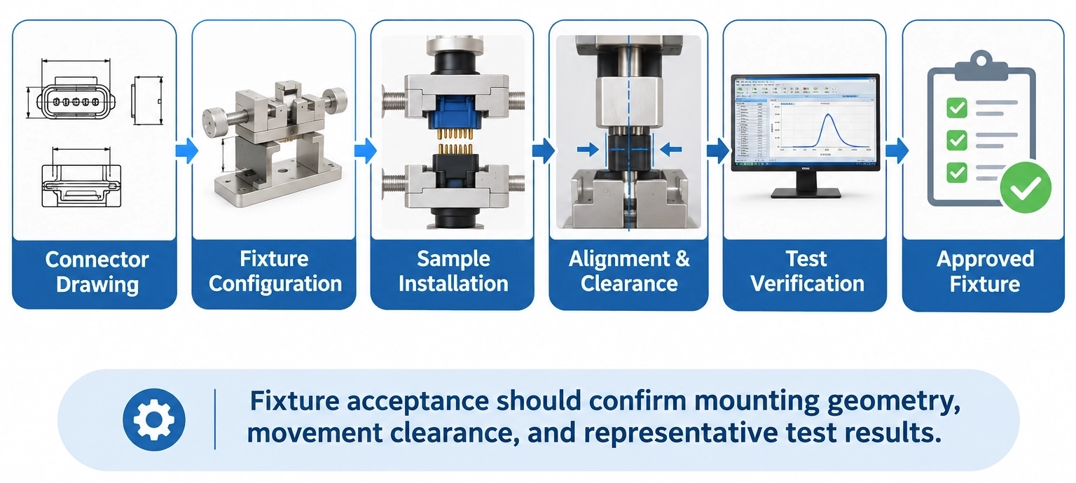
How to Validate a Connector Test Fixture
A fixture should not be accepted solely because the machine can complete an insertion and extraction cycle.
The accepted configuration must reproduce the required mounting condition and allow representative measurements.
Connector Fixture Acceptance Checklist
| Verification Item | Acceptance Requirement |
|---|---|
| Specimen mounting | Approved connector geometry is held correctly |
| Mounting datum | Required locating surfaces are used |
| Mating-axis alignment | Specified orientation is maintained |
| Housing support | No unintended deformation or slipping |
| Functional clearance | Latches, seals, and guides remain unobstructed |
| Usable travel | Required mating movement can be completed |
| Measurement review | Representative force data is available where required |
| Reinstallation | Fixture positioning can be reproduced where specified |
| Documentation | Approved configuration and test conditions are recorded |
The supplier and customer should agree on acceptance criteria before manufacturing a dedicated fixture.
Universal numerical tolerances should not be assumed for all connector types.
Practical Validation Sequence
Review the specimen. Confirm the connector drawing, mating pair, mounting geometry, and applicable procedure.
Verify the fixture. Install the approved sample and check locating surfaces, alignment, and clearance.
Perform representative tests. Use the agreed test conditions and review the measured force data.
Check setup consistency. Where required, repeat the test or reinstall the fixture to verify the mounting condition.
Document acceptance. Record the approved fixture arrangement, test settings, and supporting evidence.
Applicable Standards and Test Methods
Connector fixture design should follow the requirements of the applicable test procedure rather than a universal mounting arrangement.
Relevant references may include:
-
EIA-364-13: Connector mating and unmating force test procedures.
-
IEC 60512-13-1: Mechanical operation testing involving engagement and separation forces.
-
IEC 60512-13-2: Insertion and withdrawal force testing for specified connector contact arrangements.
-
Customer or OEM procedures: Application-specific mounting, movement, conditioning, and acceptance requirements.
These methods do not necessarily specify identical fixture arrangements or test conditions.
The applicable edition, specimen configuration, and acceptance requirements should be confirmed before equipment selection.
Mentioning a standard does not establish that every fixture or RS-6600A configuration complies with it. Compliance must be evaluated against the actual method and equipment setup.
Connector Fixture Configuration for the ITM-LAB RS-6600A
The ITM-LAB RS-6600A is a servo-controlled testing system used for connector insertion, extraction, and related mechanical force measurements.
The actual equipment includes an upper gripping assembly and a lower adjustable fixture structure.
These provide the mechanical basis for positioning and holding a mating connector pair.
Depending on the specimen, standard grips or application-specific fixture arrangements may be considered.
The final configuration should be reviewed against the connector geometry, expected force, required travel, test method, and measurement requirements.
What Should Be Confirmed Before Quotation?
The engineering review should establish:
-
How both connector halves will be mounted.
-
Which surfaces can safely support the fixture load.
-
How the intended mating axis will be maintained.
-
Whether additional positioning or clearance is required.
-
Whether seals, latches, or guides could be obstructed.
-
Whether the selected force measurement range and usable travel are suitable.
-
What test data and acceptance documentation are required.
The available fixture options and delivery scope should be confirmed for the specific project.
Related Equipment: ITM-LAB RS-6600A Servo Control Automatic Tester
Need a Fixture for Your Connector?
Send ITM-LAB your connector drawing or sample photographs, mating direction, expected force range, and applicable test method.
Our engineering team can review the mounting requirements and help determine whether a standard or dedicated fixture is appropriate.
Discuss Your Connector Fixture Requirements
What Information Is Needed for Fixture Selection?
A complete fixture drawing is not required before requesting an initial technical review.
The following information is useful:
| Information | Purpose |
|---|---|
| Connector drawing or sample photos | Identify geometry and mounting surfaces |
| Complete mating pair | Confirm the actual test interface |
| Mating direction | Establish the load axis |
| Expected force range | Support measurement system selection |
| Required travel | Verify movement and clearance |
| Applicable test method | Define the required test conditions |
| Latch condition | Identify the intended mechanical event |
| Testing frequency | Assess fixture stability and handling needs |
If some information is unavailable, the project can begin with the connector drawing or sample photographs and the intended measurement.
Additional details can be confirmed during the technical review.
For a broader equipment purchasing checklist, see ITM-LAB's existing guide, How to Specify a Connector Insertion & Extraction Force Tester in an RFQ.
FAQ
Can one connector test fixture accommodate different connector sizes?
Sometimes. Adjustable or interchangeable fixtures may accommodate multiple connector types when their mounting surfaces and required test conditions are compatible.
Each setup must still be verified for alignment, clearance, and secure mounting.
Does an X-Y platform automatically correct connector misalignment?
No. It provides positional adjustment but does not automatically correct angular misalignment, incorrect mounting datums, or specimen deformation.
The final mating geometry must be verified.
Is a custom fixture necessary for every multi-pin connector?
No. Standard grips may be suitable when the housing can be supported securely and the required mating movement can be maintained.
A custom fixture becomes appropriate when standard arrangements cannot reproduce the specified mounting condition.
Can the fixture change the measured insertion force?
Yes. Incorrect clamping, side loading, housing deformation, or fixture interference can introduce additional resistance.
The setup should be checked before interpreting an unexpected force result.
Do PCB-mounted connectors require special fixtures?
They may. Where the approved test condition includes the mounted PCB assembly, suitable board support may be necessary.
The fixture should reproduce the required installation condition rather than assume that direct gripping of the connector body is acceptable.
How can I confirm whether the RS-6600A is suitable for my connector?
Provide the mating pair drawing or sample photographs, expected force range, required travel, and applicable test method.
ITM-LAB can review these details to assess the appropriate machine and fixture configuration.
Conclusion: Configure the Fixture Around the Connector
Reliable connector mating and unmating force measurements depend on more than the force tester itself.
The fixture must hold the mating halves securely, maintain the intended axis, provide sufficient movement clearance, and avoid introducing unintended mechanical resistance.
Standard fixtures may be adequate for straightforward connector geometries. More complex applications may require adjustable positioning, dedicated supports, or custom fixtures.
The correct configuration should be selected according to the connector design, mounting condition, and approved test method.
Get a Connector Test Fixture & RS-6600A Configuration Proposal
If you are evaluating a connector force testing system, send ITM-LAB your connector drawing or sample photographs, mating direction, expected force range, and testing requirements.
Our engineering team can review the application and help identify a suitable fixture and equipment configuration.
