
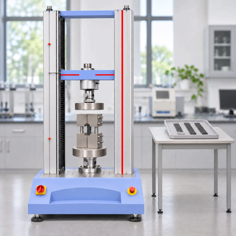
A 50 kN universal testing machine (UTM) can be suitable for ASTM D6641 if the highest expected coupon load leaves adequate margin within the verified limits of the complete compression setup. Estimate peak force from the coupon’s cross-section and expected compressive strength. Then check the load cell, combined loading compression (CLC) fixture and platens. A coupon expected to reach 55 kN already calls for a frame above 50 kN.
Is a 50 kN or 100 kN UTM enough for ASTM D6641?
Start with the highest load you expect across the coupons in your test program. Use prior test results or an upper estimate of compressive strength in the planned loading direction. If you are using material data from another source, check that the layup and test conditions are comparable.
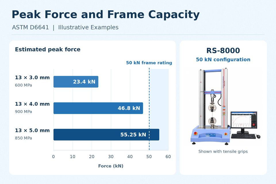
Estimated peak force (kN) = coupon width (mm) × laminate thickness (mm) × expected compressive strength (MPa) ÷ 1,000
For a rectangular coupon, use the measured width and laminate thickness in the unsupported gauge section when the specimen is available. At the quotation stage, use the drawing dimensions and account for the expected variation. Use the full thickness over the tabs separately when checking whether a tabbed coupon fits the fixture. The examples below use a 13 mm nominal width and hypothetical material properties. ASTM D6641/D6641M-23 · Intertek strength calculation overview
| Illustrative coupon | Expected compressive strength | Estimated peak force | What to evaluate |
|---|---|---|---|
| 13 mm wide × 3.0 mm thick | 600 MPa | 23.4 kN | Consider a suitable RS-8000 configuration. Check that the selected compression load cell covers the expected force range and that the fixture fits the coupon. |
| 13 mm wide × 5.0 mm thick | 850 MPa | 55.25 kN | Evaluate the 100 kN RS-8000A. Check that the fixture accepts the specimen thickness, including tabs if used, and that every component in the compression load path covers the required force. |
What if the estimate is close to 50 kN? A 13 × 4.0 mm coupon at 900 MPa gives 46.8 kN, leaving just 3.2 kN below a 50 kN frame rating before allowing for variation. Check the upper expected load, required margin and verified compression range of the load cell. Then confirm the rated loads of the fixture, platens and any adapters. If the 50 kN configuration cannot cover those requirements, evaluate a higher-capacity setup.
ITM-LAB RS-8000 vs RS-8000A
| UTM platform | Published capacity options | When to evaluate it |
|---|---|---|
| RS-8000 | 10–50 kN | Your highest expected load and required margin fit an available configuration, and the selected load cell covers the low end of your test range. |
| RS-8000A | 100, 200 or 300 kN | Evaluate 100 kN when the required load and margin exceed the RS-8000 range. Review the 200 or 300 kN options if other work in the lab requires the extra capacity. |
These are published frame capacities. Confirm the usable load range and the fixture and instrumentation package for the specific ASTM D6641 setup in your quotation. ITM-LAB electronic universal testing machines
Request an ASTM D6641 Setup Review · Have a coupon drawing? Email it to ITM-LAB with your expected peak load.
How do you choose a CLC fixture and specify the complete setup?
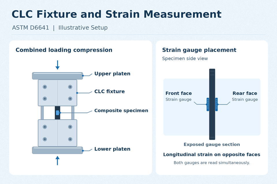
ASTM D6641 measures compressive properties of polymer matrix composites, including strength and modulus. A CLC fixture transfers force into the coupon through its ends and through shear along the clamped surfaces. Procedure A uses untabbed coupons. Procedure B uses tabbed coupons and is often used for highly directional laminates such as unidirectional composites. When sending a drawing, identify the layup, loading direction and whether the specimen has tabs. If your lab also runs ASTM D695, that method uses end loading. Specify the setup for each method in the quotation. ASTM D6641/D6641M-23 scope · ITM-LAB ASTM D695 guide
What to ask for in the equipment quotation
| Line item | What to confirm in writing |
|---|---|
| Frame and compression load cell | Frame model, load cell capacity and verified compression measurement range for the expected coupon loads. |
| CLC fixture | Fixture model, rated compression force, supported specimen dimensions and maximum total thickness at the tabs. Check access to the unsupported gauge section and space to attach sensors and route leads. |
| Platens and adapters | Mounting interface, usable platen area, component ratings and method of centering and alignment. Ask which parts are included. |
| Strain measurement | Ability to measure longitudinal strain simultaneously on opposite faces and synchronize the readings with force. If Poisson’s ratio is required, also specify transverse strain measurement. |
| Software and report | Required calculations, raw force and strain export, bending checks, failure records and a sample report. Confirm which items the software produces and which the operator records. |
A fixture’s rating can be lower than the frame’s. For example, MTS publishes an 89 kN static rating for one of its CLC fixtures and lists the platens separately. Check the ratings of the specific components on your quote to establish the usable capacity of the assembled setup. MTS CLC fixture specifications
Can you use an existing UTM for ASTM D6641?
You may be able to keep your current frame if the fixture and platens fit, the compression force can be measured over the required range, and the system can collect the needed strain data. Send these four details for a retrofit review.
- Frame and load cell — Manufacturer, model, installed load cell and available compression verification records.
- Platen interface — A drawing or clear photos showing the platen mount and dimensions.
- Compression working space — Available height with the platens installed and access for mounting the CLC fixture and connecting the strain leads.
- Data acquisition — Current controller or external acquisition hardware, available strain channels and how force and strain data are synchronized.
Ask the supplier to identify the components you can reuse and the items that need to be added or replaced. Instron ASTM D6641 equipment setup
How do you verify a valid compression result?
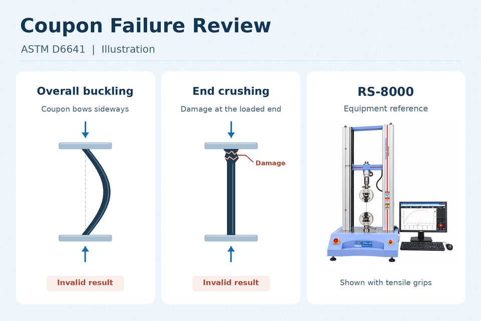
Review both the coupon after the test and the strain data during loading. Premature end crushing, overall Euler buckling and failure within the clamped region invalidate the result. Record the failure mode and location, and compare the strain readings from opposite faces against the bending criteria in the applicable ASTM edition. If the readings diverge unexpectedly, also check for instrumentation issues such as a detached gauge or lead. ASTM D6641/D6641M-23 · ZwickRoell failure and bending assessment
Plan for two simultaneous longitudinal strain readings. Under ASTM D6641/D6641M-23, single-sided measurement on specimens after the first five is permitted only under specified conditions, including unchanged specimens and procedure, use of the same fixture and frame, and acceptable bending on the first five. Follow the instrumentation requirements in the edition specified by your test plan. ASTM D6641/D6641M-23, Section 7.7
If your equipment acceptance includes a trial, agree in advance on the coupon, the raw data and calculations to be delivered, and how the report will document bending and failure location.
What should you send with an ASTM D6641 equipment RFQ?
Start with the coupon drawing, highest expected peak load and required outputs. Include the following if available.
- Test plan — ASTM edition, Procedure A or B if specified, and test conditions.
- Specimen details — Material, layup, loading direction, coupon dimensions and tab dimensions.
- Force requirements — Expected peak load or estimated compressive strength and the range of specimen widths and thicknesses.
- Report requirements — Strength, modulus or other requested results, plus any raw data and report format requirements.
- Existing equipment — UTM model and installed hardware if you want to reuse your frame.
Contact ITM-LAB about your ASTM D6641 setup. Send drawings or previous test results to sales2@itm-lab.com. Let us know whether you need a new system or a review of your existing equipment.
FAQ
- Can I run ASTM D6641 with compression platens alone?
A conventional platen-mounted setup uses the platens to apply compression to the CLC fixture. The fixture then introduces the combined end and shear loading into the specimen. Instron CLC fixture overview
- Can crosshead travel be used to calculate compressive modulus?
Use the strain measured on the specimen in the gauge section. Crosshead travel includes deformation of the machine and components in the load path. Direct specimen readings also let you check bending during loading. ZwickRoell strain measurement overview
- Does a 100 kN UTM need a 100 kN CLC fixture?
Size the fixture for the required test load and margin. A lower-rated fixture can be suitable if it covers the planned loads. Set the permissible force for the complete setup based on the ratings of the frame, load cell, fixture, platens and adapters. Example CLC fixture rating
