
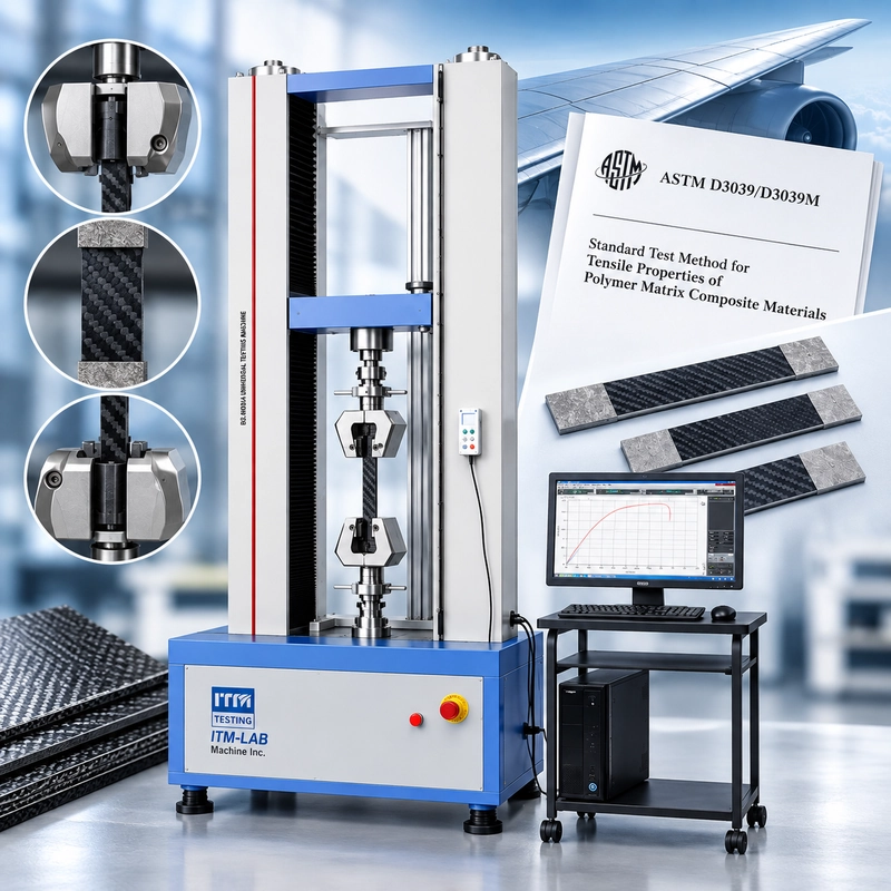
A 15 mm-wide carbon-fiber coupon does not look like a 40 kN specimen.
It can be.
That catches people out when they first specify an ASTM D3039 tensile testing system. The coupon is small, but a small cross-section combined with high laminate strength can put the failure load well into the tens of kilonewtons.
Force capacity is only the first problem.
If the specimen slips, is damaged near the grip, bends because of poor alignment, or fails beside a poorly loaded tab, a perfectly calibrated load cell can still produce a result that deserves a second look.
A good ASTM D3039 setup therefore starts with the specimen—not the machine.
This guide looks at the practical decisions behind ASTM D3039 composite tensile testing: expected force, gripping and load introduction, tabs, alignment, strain measurement, failure behavior, and how those requirements translate into a complete tensile test system.
What ASTM D3039 Is Actually Measuring
The current active edition, ASTM D3039/D3039M-17(2025), covers the determination of in-plane tensile properties of polymer matrix composites reinforced by high-modulus fibers. Within the scope of the method, the composite forms are limited to continuous- or discontinuous-fiber reinforced materials with laminates that are balanced and symmetric with respect to the test direction.
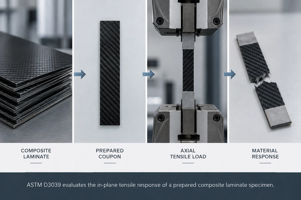
In practical terms, the test path is straightforward:
Composite laminate → Prepared coupon → Axial tensile load → Material response
Depending on the test program, properties obtained using D3039 can include ultimate tensile strength, ultimate tensile strain, tensile chord modulus, Poisson's ratio, and transition strain.
That creates an important distinction when specifying equipment.
A laboratory interested primarily in ultimate tensile strength does not necessarily need the same measurement configuration as a laboratory that also needs modulus or Poisson's ratio.
So when an RFQ says only:
ASTM D3039 tensile testing machine required.
we still need to know quite a bit.
What laminate is being tested? What are the coupon dimensions? What force is expected? How will the specimen be gripped? Does the laboratory need strength only, or strain-based properties as well?
Those questions define the test system.
Start With the Coupon, Not the Machine
Here is where a simple calculation becomes useful.
For an initial equipment estimate:
Expected Tensile Force ≈ Cross-Sectional Area × Expected Tensile Stress
For a rectangular coupon:
Cross-Sectional Area = Width × Thickness
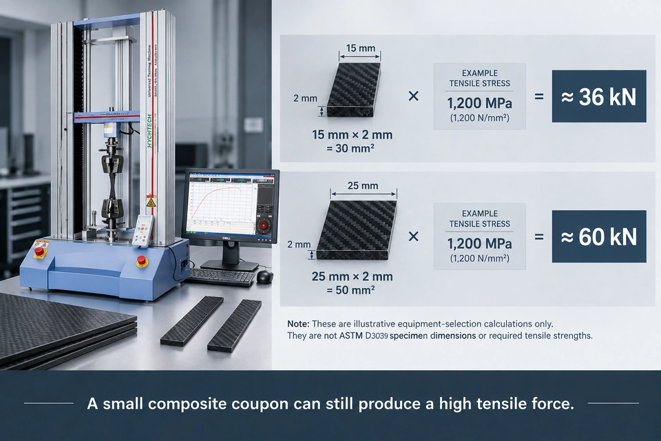
Take an illustrative specimen that is:
15 mm wide × 2.0 mm thick
Its cross-sectional area is:
15 × 2.0 = 30 mm²
Now assume the laminate is expected to fail at approximately:
1,200 MPa
Because 1 MPa = 1 N/mm²:
30 mm² × 1,200 N/mm² ≈ 36,000 N
The estimated failure force is therefore:
≈ 36 kN
The specimen is small. The force may not be.
Now make the same example laminate 25 mm wide while keeping the 2 mm thickness:
25 × 2 = 50 mm²
At the same illustrative tensile stress:
50 mm² × 1,200 N/mm² ≈ 60,000 N
or:
≈ 60 kN
Same example material. Same thickness. Still a relatively small coupon.
Very different machine requirement.
These numbers are illustrative equipment-sizing calculations only. They are not ASTM D3039 specimen dimensions, prescribed tensile strengths, or acceptance criteria.
ASTM also identifies factors such as material preparation, lay-up, stacking sequence, specimen preparation, conditioning, environment, alignment, gripping, test speed, void content, and reinforcement volume as variables that can influence tensile response.
So the useful starting sequence is:
Laminate → Specimen dimensions → Expected tensile stress → Expected force
Not:
ASTM D3039 → Machine capacity
Getting the Load Into the Laminate
Enough machine capacity does not guarantee a good composite tensile test.
The machine still has to transfer that force into the laminate.
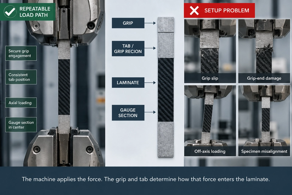
Think about the load path:
Machine → Grip → Tab / Grip Region → Laminate → Gauge Section
If the grip cannot hold the specimen, it slips.
If the gripping arrangement damages the laminate, failure may start where the specimen is being held rather than where its tensile response is intended to be evaluated.
If load enters unevenly, the grip region can become the dominant problem in the test.
This is where tabs enter the discussion.
What Is the Tab Solving?
Tabs are common in composite tensile testing, but they are not a universal checkbox for every D3039 specimen.
Public D3039 testing guidance notes that tabs are not mandatory in every case, while also describing their use as recommended for unidirectional materials. In practice, tabs can help protect the composite from grip damage and improve load transfer into the specimen.
The engineering objective is simple:
Transfer the required tensile load without creating a new failure problem at the grip.
Tab material, geometry, bonding, specimen surface, grip pressure, and jaw interaction can all affect that load transfer.
Good tabs do not rescue poor alignment, either.
The intended loading condition is axial. Conceptually:
Machine axis ≈ Grip axis ≈ Specimen axis
An offset specimen, angular misalignment, or inconsistent clamping can introduce bending into what is intended to be a tensile test. ASTM specifically identifies specimen alignment and gripping among the factors that can influence tensile response.
One useful diagnostic question is:
Where does the coupon keep breaking?
If specimens repeatedly fail where the machine is holding them, rather than in the intended test region, look at the setup before simply increasing grip pressure.
The complete load path deserves attention.
Specimen Dimensions Are Part of the Result
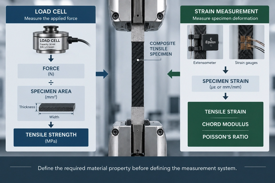
The load cell measures force.
It does not directly measure tensile strength.
For a rectangular composite coupon, tensile stress is based on force relative to the specimen's original cross-sectional area:
Tensile Stress = Force / Original Cross-Sectional Area
Width and thickness therefore affect the calculated material result.
This matters because even an excellent force measurement cannot compensate for an incorrect specimen area.
If the entered thickness is wrong, the load cell can report force correctly while the calculated tensile stress is wrong.
Practical D3039 testing guidance describes measuring specimen width and thickness at multiple locations in the gauge section and using the measurements to establish cross-sectional area.
For composite coupons, dimensional measurement also deserves care when specimen surfaces are not perfectly uniform.
It is a small part of the overall setup, but it feeds directly into the final stress calculation.
Strength Only—or Do You Need Modulus Too?
This question can change the test system.
Suppose Laboratory A needs:
Ultimate tensile strength
Laboratory B needs:
Ultimate tensile strength + tensile strain + chord modulus + Poisson's ratio
Both are running ASTM D3039 tests.
They do not necessarily need the same measurement configuration.
A load cell provides force.
Specimen width and thickness allow that force to be expressed as stress.
Modulus needs something else:
a suitable measurement of specimen strain.
For D3039 applications, public testing guidance describes the use of strain gauges and extensometry for strain measurement. Where Poisson's ratio is required, transverse as well as longitudinal strain information is needed.
Machine crosshead movement should therefore not automatically be treated as specimen gauge-section strain.
Crosshead displacement can include movement or compliance elsewhere in the test system. When strain-based properties matter, the strain-measurement method should be selected around the property being determined.
That gives us two separate equipment questions:
How much force must the system measure?
and
How must specimen deformation be measured?
For a strength-only program, the second question may be relatively simple.
For modulus, strain, or Poisson's ratio, it becomes part of the core system specification.
The Broken Coupon Is Part of the Result
The machine stops at 42.8 kN.
Before copying 42.8 kN into the spreadsheet, look at the coupon.
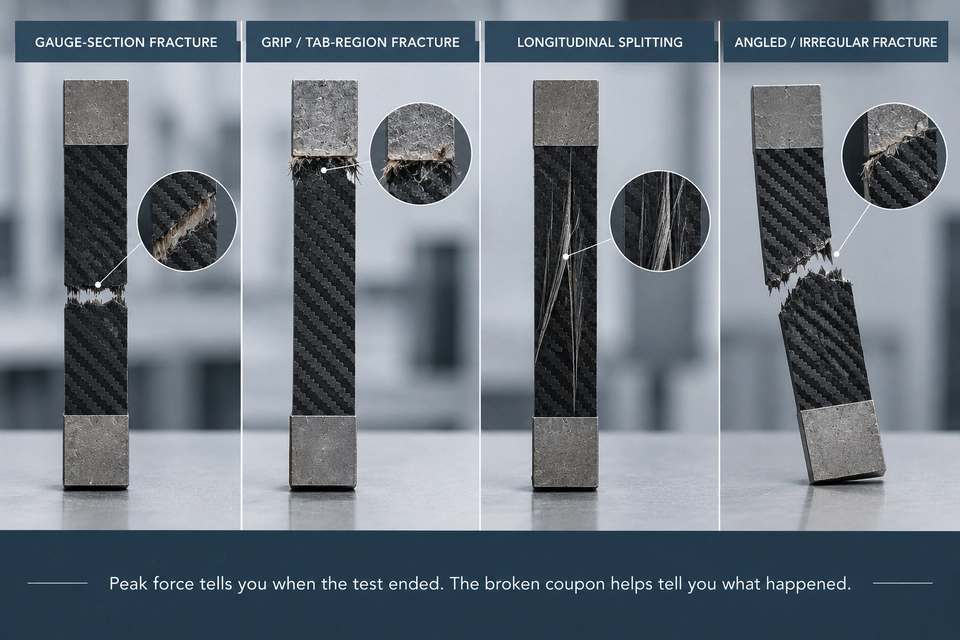
Where did it fail?
Was there visible damage near the grip?
Did the specimen split longitudinally?
Did it fracture at an angle?
Was the failure concentrated around a tab or grip region?
Similar peak-force values can come from mechanically different events.
ASTM D3039 uses a structured failure-mode identification approach, so failure location and appearance should be recorded and interpreted rather than reducing every test to a single maximum-force value.
That does not mean an unusual-looking fracture should automatically be discarded.
It means the force value and the physical specimen belong in the same interpretation.
Repeated failure close to the grip should prompt a look at load introduction, alignment, tab condition, gripping, and specimen preparation.
This becomes particularly useful while developing a new setup.
If several coupons repeatedly fail in the same unintended location, the test may be telling you something about the setup before it tells you something about the laminate.
Peak force tells you when the test ended. The broken coupon helps tell you what happened.
A 49.5 kN Specimen and a 50 kN Machine
Now consider a practical equipment inquiry.
A customer sends:
| Test Requirement | Information |
|---|---|
| Standard | ASTM D3039 |
| Material | CFRP laminate |
| Specimen Width | 15 mm |
| Specimen Thickness | 2.2 mm |
| Expected Tensile Strength | 1,500 MPa |
| Required Results | Tensile strength + modulus |
| Test Volume | 30 specimens/day |
Start with the cross-section:
15 mm × 2.2 mm = 33 mm²
Then make an initial force estimate:
33 mm² × 1,500 N/mm² = 49,500 N
or:
≈ 49.5 kN
Again, this is an illustrative equipment-sizing example, not an ASTM D3039 prescribed specimen or force.
Now comes the important part.
The ITM-LAB RS-8000 range extends to 50 kN.
Does an estimated 49.5 kN failure force automatically make a 50 kN RS-8000 the correct system?
The calculation does not establish that.
It tells us the expected specimen failure load is already close to the upper capacity of that configuration.
We still need to understand the likely upper force, specimen variability, final dimensions, gripping arrangement, and load-cell working range.
And this customer needs modulus, so strain measurement still has to be defined.
Before configuring the system, useful follow-up information would include:
What is the expected upper specimen force?
What laminate and fiber direction are being tested?
How much specimen-to-specimen variation is expected?
Are tabs used?
What gripping arrangement is required?
How will strain be measured?
Is testing limited to ambient laboratory conditions?
If non-ambient testing is part of the program, that should also be defined before the final system configuration because the available test space, grips, and strain-measurement arrangement may be affected.
The key distinction is:
A calculated 49.5 kN expected failure load is not the same thing as automatically specifying a 50 kN test system.
RS-8000 or RS-8000A?
For composite tensile applications, ITM-LAB offers two relevant universal testing machine capacity ranges:
RS-8000: 10–50 kN
RS-8000A: 100–300 kN
The selection should not be reduced to:
Small coupon → RS-8000
Large coupon → RS-8000A
Nor should it be:
GFRP → RS-8000
CFRP → RS-8000A
The material name alone does not determine machine capacity.
The specimen and expected load do.
Start with:
Width × Thickness
↓
Cross-Sectional Area
↓
Area × Expected Tensile Stress
↓
Expected Force
Then consider:
Load Cell → Grips / Tabs → Alignment → Strain Measurement → Travel / Test Space
For composite specimens whose expected force and complete measurement requirements fit appropriately within the 10–50 kN range, the RS-8000 can be evaluated.
For higher-force configurations or laboratories requiring a substantially higher-capacity platform, the 100–300 kN RS-8000A range can be evaluated.
Maximum capacity is not the only consideration.
If most daily specimens are tested at much lower forces, load-cell selection still matters. Grips must suit the specimen. Strain measurement must suit the required property.
The objective is a balanced measurement system—not simply the largest frame available.
What to Send With an ASTM D3039 RFQ
You do not need a finished laboratory specification before contacting us.
But:
ASTM D3039, please quote.
is not enough information to configure the system properly.
A useful first RFQ includes:
- composite material and reinforcement type;
- laminate / lay-up and test direction;
- specimen drawing, if available;
- specimen width, thickness, and length;
- expected tensile strength or expected failure force;
- tabbed or untabbed specimen information;
- required results: strength only, or strength plus strain / modulus / Poisson's ratio;
- test temperature or environmental requirement;
- approximate number of tests per day.
If the gripping arrangement or strain-measurement method has already been defined, include that as well.
For unusual specimens, a drawing or physical sample can be much more useful than the phrase "carbon-fiber tensile test."
The goal is to configure the machine around the test—not make the test fit a machine selected too early.
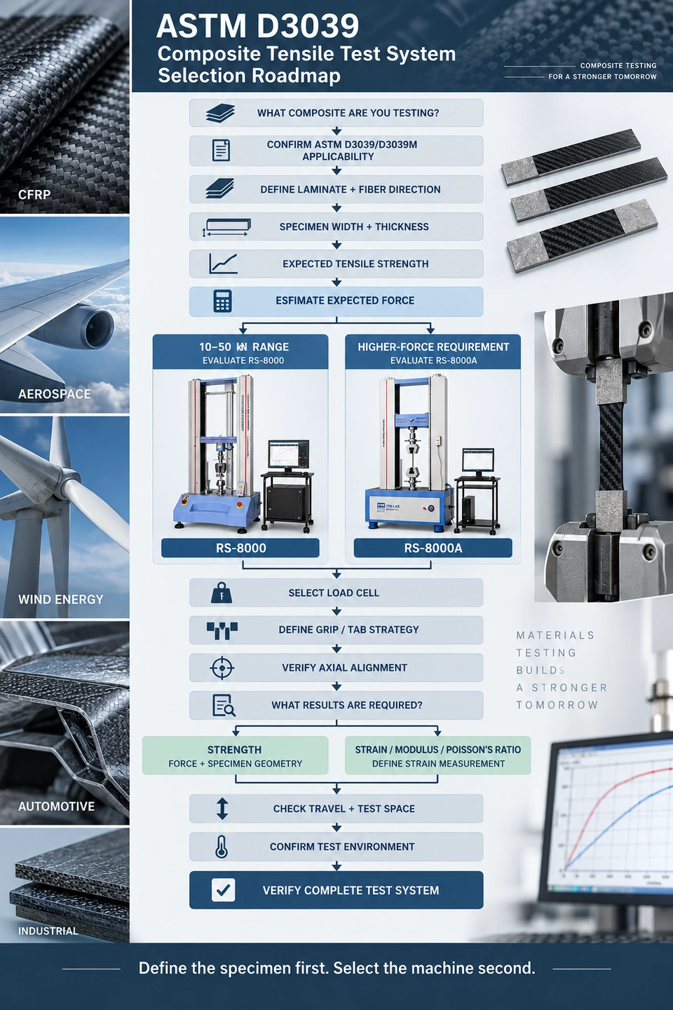
ASTM D3039 Composite Tensile Test System Selection Roadmap
ASTM D3039 Composite Tensile Testing FAQ
What is ASTM D3039 used for?
ASTM D3039/D3039M is used to determine in-plane tensile properties of polymer matrix composite materials reinforced by high-modulus fibers within the scope of the method. The resulting data can be used for material specification, research and development, quality assurance, and structural design and analysis.
How do I estimate the machine capacity for an ASTM D3039 test?
A useful first estimate is:
Expected Force ≈ Specimen Width × Specimen Thickness × Expected Tensile Stress
This provides an approximate specimen-force requirement. Final system selection should also consider the expected upper force, load-cell working range, grips, tabs where applicable, strain measurement, and available test space.
Why can a small CFRP coupon require a high-force tensile testing machine?
Because the required force depends on both the specimen cross-sectional area and the tensile stress developed by the laminate.
For example, a 30 mm² specimen reaching an illustrative 1,200 MPa corresponds to approximately 36 kN. Small physical dimensions do not necessarily mean a low-force test.
Are tabs required for ASTM D3039?
Not for every specimen configuration. Public D3039 testing guidance notes that tabs are not mandatory in all cases and describes them as recommended for unidirectional materials. Their practical role is to help manage load transfer and reduce grip-related specimen damage.
How is strain measured in ASTM D3039 testing?
Suitable extensometry or strain-gauge arrangements may be used depending on the required property and specimen configuration. Where Poisson's ratio is required, both longitudinal and transverse strain information is needed.
Why does a composite tensile specimen keep breaking near the grip?
Repeated grip-region failure can justify checking the gripping arrangement, tab condition, load introduction, alignment, and specimen preparation. The peak-force value should be reviewed together with the location and appearance of the fracture.
Can the RS-8000 be used for ASTM D3039?
The RS-8000 covers 10–50 kN. It can be evaluated when the expected specimen forces and the rest of the measurement requirements fit appropriately within that system range. ASTM D3039 itself does not determine the required machine capacity.
When should I consider the RS-8000A?
The RS-8000A covers 100–300 kN and can be evaluated for higher-force composite specimens or laboratories that require a broader high-capacity platform. Load-cell selection, gripping, strain measurement, specimen geometry, and test-space requirements still need to be considered.
Build the Test Around the Specimen
ASTM D3039 defines the test method.
It does not mean every composite laboratory needs the same tensile machine.
One laboratory may be testing relatively low-force coupons for tensile strength.
Another may have high-strength CFRP specimens approaching the upper end of a 50 kN system.
A third may need strength, modulus, and Poisson's ratio across several laminate configurations.
All three can be working with ASTM D3039.
Their equipment requirements can be different.
A more useful selection path is:
Laminate → Specimen Geometry → Expected Force → Load Cell → Gripping / Tabs → Alignment → Strain Measurement → Machine
For ITM-LAB, the RS-8000 (10–50 kN) and RS-8000A (100–300 kN) provide two capacity ranges that can be evaluated around different composite tensile requirements.
If you are planning an ASTM D3039 test system, send us your laminate information, specimen drawing, width, thickness, expected tensile strength, required results, and test environment.
Those details tell us far more about the right test system than the standard number alone.
